Model Definition and Configuration
7-15
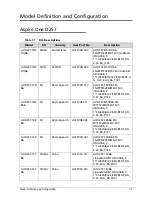
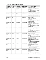
AOD257-13D
kk
EMEA
Middle East
LU.SFS0D.053
AOD257-13Dkk EM
SNW7ST32EMSSME6 MC
UMACkk_3
1*1G/250/6L2.2/5R/CBSDS_GN_
0.3C_IRB_ES61
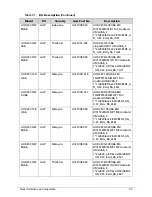
AOD257-13D
kk
EMEA
Middle East
LU.SFS0D.052
AOD257-13Dkk EM
SNW7ST32EMSSME4 MC
UMACkk_3
1*1G/250/6L2.2/5R/CBSDS_GN_
0.3C_IRB_ES61
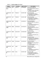
AOD257-13D
kk
EMEA
Middle East
LU.SFS0D.051
AOD257-13Dkk EM
SNW7ST32EMSSME3 MC
UMACkk_3
1*1G/250/6L2.2/5R/CBSDS_GN_
0.3C_IRB_ES81
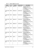
AOD257-13D
kk
EMEA
Middle East
LU.SFS0D.050
AOD257-13Dkk EM
SNW7ST32EMSSME2 MC
UMACkk_3
1*1G/250/6L2.2/5R/CBSDS_GN_
0.3C_IRB_ARA1
AOD257-13D
kk
EMEA
Middle East
LU.SFS0D.049
AOD257-13Dkk EM
SNW7ST32EMSSME1 MC
UMACkk_3
1*1G/250/6L2.2/5R/CBSDS_GN_
0.3C_IRB_ARA1
AOD257-13D
kk
EMEA
Middle East
LU.SFS0D.048
AOD257-13Dkk EM
SNW7ST32EMSSME1 MC
UMACkk_3
1*1G/250/6L2.2/5R/CBSDS_GN_
0.3C_IRB_AR91
AOD257-13D
kk
EMEA
Algeria
LU.SFS0D.047
AOD257-13Dkk EM
SNW7ST32EMSSDZ1 MC
UMACkk_3
1*1G/250/6L2.2/5R/CBSDS_GN_
0.3C_IRB_ARB1
AOD257-13D
kk
EMEA
South Africa
LU.SFS0D.046
AOD257-13Dkk EM
SNW7ST32EMSSZA5 MC
UMACkk_3
1*1G/250/6L2.2/5R/CBSDS_GN_
0.3C_IRB_ES61
AOD257-13D
kk
EMEA
South Africa
LU.SFS0D.045
AOD257-13Dkk EM
SNW7ST32EMSSZA2 MC
UMACkk_3
1*1G/250/6L2.2/5R/CBSDS_GN_
0.3C_IRB_ES61
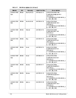
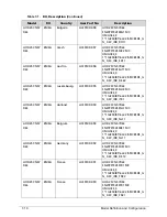
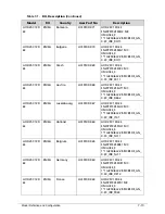
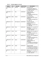
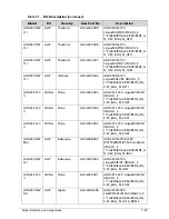
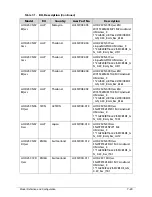
Table 7-1.
RO, Description
(Continued)
Model
RO
Country
Acer Part No
Description
Summary of Contents for AOHAPPY2
Page 1: ...Aspire One D257 Happy 2 SERVICEGUIDE ...
Page 10: ...x ...
Page 11: ...CHAPTER 1 Hardware Specifications ...
Page 14: ...1 4 ...
Page 55: ...CHAPTER 2 System Utilities ...
Page 81: ...CHAPTER 3 Machine Maintenance Procedures ...
Page 83: ...3 3 Camera Module Installation 3 40 ...
Page 84: ...3 4 ...
Page 107: ...Machine Maintenance Procedures 3 27 ID Size Quantity Screw Type C M2 0 3 0 NI 2 ...
Page 116: ...3 36 Machine Maintenance Procedures Figure 3 33 LCD Panel ...
Page 121: ...CHAPTER 4 Troubleshooting ...
Page 127: ...Troubleshooting 4 7 9 If the issue is still not resolved refer to Online Support Information ...
Page 144: ...4 24 Troubleshooting ...
Page 145: ...CHAPTER 5 Jumper and Connector Locations ...
Page 152: ...5 8 Jumper and Connector Locations ...
Page 153: ...CHAPTER 6 FRU Field Replaceable Unit List ...
Page 154: ...6 2 Exploded Diagrams 6 4 FRU List 6 7 Screw List 6 28 ...
Page 181: ...CHAPTER 7 Model Definition and Configuration ...
Page 182: ...1 2 Aspire One D257 7 1 Aspire One Happy 2 7 109 ...
Page 388: ...7 206 Model Definition and Configuration ...
Page 389: ...CHAPTER 8 Test Compatible Components ...
Page 390: ...8 2 Microsoft Windows 7 Environment Test 8 4 ...
Page 398: ...8 10 Test Compatible Components ...
Page 399: ...Test Compatible Components 8 11 ...
Page 400: ...8 12 Test Compatible Components ...
Page 401: ...CHAPTER 9 Online Support Information ...
Page 402: ...9 2 Introduction 9 3 ...
Page 404: ...9 4 Online Support Information ...

