System Utilities
2-3
System Utilities
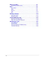
BIOS Setup Utility
0
This utility is a hardware configuration program built into a computer’s BIOS (Basic
Input/Output System).
The utility is pre-configured and optimized so most users do not need to run it. If
configuration problems occur, the setup utility may need to be run. Refer to
Chapter 4,
Troubleshooting
when a problem arises.
To activate the utility, press
F2
during POST (power-on self-test) when prompted at the
bottom of screen.
The default parameter of
F12 Boot Menu
is set to
Disabled
.
To change the boot
device without entering
BIOS Setup Utility
, set the parameter to
Enabled
.
To change the boot device without entering the BIOS SETUP, press
F12
during POST to
enter the multi-boot menu.
Navigating the BIOS Utility
0
Six menu options are:
Information
Main
Security
Boot
Exit
To navigate through the following:
Menu - use the left and right arrow keys
Item - use the up and down arrow keys
Change parameter value - press
F5
or
F6
.
Exit - Press
Esc
Load default settings - press
F9
. Press
F10
to save changes and exit BIOS Setup
Utility
NOTE:
NOTE
:
Parameter values can be changed if enclosed in square brackets open the
DIMM door open the DIMM door[ ]. Navigation keys appear at the bottom
of the screen. Read parameter help carefully when making changes to
parameter values. Parameter help is found in the Item Specific Help area of
the screen.
NOTE:
NOTE
:
System information is subject to specific models.
Summary of Contents for AOHAPPY2
Page 1: ...Aspire One D257 Happy 2 SERVICEGUIDE ...
Page 10: ...x ...
Page 11: ...CHAPTER 1 Hardware Specifications ...
Page 14: ...1 4 ...
Page 55: ...CHAPTER 2 System Utilities ...
Page 81: ...CHAPTER 3 Machine Maintenance Procedures ...
Page 83: ...3 3 Camera Module Installation 3 40 ...
Page 84: ...3 4 ...
Page 107: ...Machine Maintenance Procedures 3 27 ID Size Quantity Screw Type C M2 0 3 0 NI 2 ...
Page 116: ...3 36 Machine Maintenance Procedures Figure 3 33 LCD Panel ...
Page 121: ...CHAPTER 4 Troubleshooting ...
Page 127: ...Troubleshooting 4 7 9 If the issue is still not resolved refer to Online Support Information ...
Page 144: ...4 24 Troubleshooting ...
Page 145: ...CHAPTER 5 Jumper and Connector Locations ...
Page 152: ...5 8 Jumper and Connector Locations ...
Page 153: ...CHAPTER 6 FRU Field Replaceable Unit List ...
Page 154: ...6 2 Exploded Diagrams 6 4 FRU List 6 7 Screw List 6 28 ...
Page 181: ...CHAPTER 7 Model Definition and Configuration ...
Page 182: ...1 2 Aspire One D257 7 1 Aspire One Happy 2 7 109 ...
Page 388: ...7 206 Model Definition and Configuration ...
Page 389: ...CHAPTER 8 Test Compatible Components ...
Page 390: ...8 2 Microsoft Windows 7 Environment Test 8 4 ...
Page 398: ...8 10 Test Compatible Components ...
Page 399: ...Test Compatible Components 8 11 ...
Page 400: ...8 12 Test Compatible Components ...
Page 401: ...CHAPTER 9 Online Support Information ...
Page 402: ...9 2 Introduction 9 3 ...
Page 404: ...9 4 Online Support Information ...


