7-42
Model Definition and Configuration
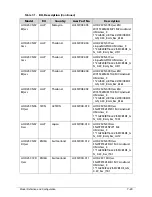
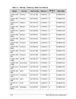
AOD257-13D
kk
USA
LU.SFS0D.001
ATMN455B
NLED10.1WSVGAGS
AOD257-N57
DQrr
Switzerland
LU.SG40D.008
ATMN570B
NLED10.1WSVGAGS
AOD257-13D
Qrr
GCTWN
LU.SG40D.007
ATMN455B
NLED10.1WSVGAGS
AOD257-N57
DQrr
GCTWN
LU.SG40D.006
ATMN570B
NLED10.1WSVGAGS
AOD257-N57
8Qrr
Thailand
LU.SG408.006
ATMN570B
NLED10.1WSVGAGS
AOD257-N57
8Qrr
Thailand
LU.SG408.005
ATMN570B
NLED10.1WSVGAGS
AOD257-N57
8Qrr
Thailand
LU.SG408.004
ATMN570B
NLED10.1WSVGAGS
AOD257-N57
Crr
Thailand
LU.SG40C.009
ATMN570B
NLED10.1WSVGAGS
AOD257-N57
Crr
Thailand
LU.SG40C.008
ATMN570B
NLED10.1WSVGAGS
AOD257-N57
Crr
Thailand
LU.SG40C.007
ATMN570B
NLED10.1WSVGAGS
AOD257-N57
Crr
Vietnam
LU.SG40C.006
ATMN570B
NLED10.1WSVGAGS
AOD257-13C
rr
China
LU.SG40C.005
ATMN455B
NLED10.1WSVGAGS
AOD257-13C
rr
China
LU.SG40C.004
ATMN455B
NLED10.1WSVGAGS
AOD257-13C
rr
China
LU.SG40C.003
ATMN455B
NLED10.1WSVGAGS
AOD257-N57
8Qrr
Indonesia
LU.SG408.003
ATMN570B
NLED10.1WSVGAGS
AOD257-N57
Crr
Indonesia
LU.SG40C.002
ATMN570B
NLED10.1WSVGAGS
AOD257-13C
rr
China
LU.SG40C.001
ATMN455B
NLED10.1WSVGAGS
AOD257-N57
Drr
Japan
LU.SG40D.005
ATMN570B
NLED10.1WSVGAGS
AOD257-13D
rr
Japan
LU.SG40D.004
ATMN455B
NLED10.1WSVGAGS
AOD257-13D
rr
Japan
LU.SG40D.003
ATMN455B
NLED10.1WSVGAGS
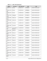
Table 1-2.
CPU, LCD (Continued)
Model
Country
Acer Part No
CPU
LCD
Summary of Contents for AOHAPPY2
Page 1: ...Aspire One D257 Happy 2 SERVICEGUIDE ...
Page 10: ...x ...
Page 11: ...CHAPTER 1 Hardware Specifications ...
Page 14: ...1 4 ...
Page 55: ...CHAPTER 2 System Utilities ...
Page 81: ...CHAPTER 3 Machine Maintenance Procedures ...
Page 83: ...3 3 Camera Module Installation 3 40 ...
Page 84: ...3 4 ...
Page 107: ...Machine Maintenance Procedures 3 27 ID Size Quantity Screw Type C M2 0 3 0 NI 2 ...
Page 116: ...3 36 Machine Maintenance Procedures Figure 3 33 LCD Panel ...
Page 121: ...CHAPTER 4 Troubleshooting ...
Page 127: ...Troubleshooting 4 7 9 If the issue is still not resolved refer to Online Support Information ...
Page 144: ...4 24 Troubleshooting ...
Page 145: ...CHAPTER 5 Jumper and Connector Locations ...
Page 152: ...5 8 Jumper and Connector Locations ...
Page 153: ...CHAPTER 6 FRU Field Replaceable Unit List ...
Page 154: ...6 2 Exploded Diagrams 6 4 FRU List 6 7 Screw List 6 28 ...
Page 181: ...CHAPTER 7 Model Definition and Configuration ...
Page 182: ...1 2 Aspire One D257 7 1 Aspire One Happy 2 7 109 ...
Page 388: ...7 206 Model Definition and Configuration ...
Page 389: ...CHAPTER 8 Test Compatible Components ...
Page 390: ...8 2 Microsoft Windows 7 Environment Test 8 4 ...
Page 398: ...8 10 Test Compatible Components ...
Page 399: ...Test Compatible Components 8 11 ...
Page 400: ...8 12 Test Compatible Components ...
Page 401: ...CHAPTER 9 Online Support Information ...
Page 402: ...9 2 Introduction 9 3 ...
Page 404: ...9 4 Online Support Information ...


