background image


4.    How to Use 


User Guide 


Page 4-36 


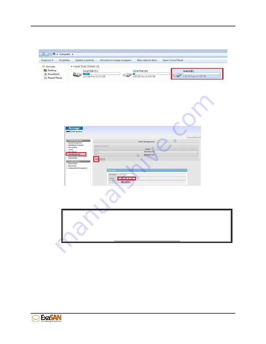
Step 7: Finally, click the “Computer” icon on your desk top. See client local hard disks 

and SAN hard disk storage location and capacity status as shown below: 


4.6.5.3


MAC Client 

4.6.5.3.1


Install SANit Client on Mac Platform 

Add each client IP to join the SAN group. Before you add a client IP, ensure that your IP 

(example:  192.168.0.233) can “Ping”  to  the  SW16  IP(example:  192.168.0.25). See the 

steps below: 


Step 1: After you download the SANit Mac client software, please follow the installation 

procedures as follows: 


Note: 

In SANit version 5.3.3, you may not find the MAC client software in the 

“Download Client Software and Document.” Future version may 

support Mac client software. Please contact your SANit supplier or visit 

the Accusys web site http://www.accusys.com.tw to learn more. 


Step 2: Double click “SANit Mac client software” to install it and then click “Continue.” 

Summary of Contents for ExaSAN SW16

Page 1: ...0 switch Model SW16 PCIe 2 0 RAID System Models A12S2 PS B08S2 PS QSFP HBA Model ACS 63200NT Z1M QSFP PCIe Cables Also includes software setup information for Switch management software Switch Web GUI SAN management software SANit Accusys Inc January 10 2013 Version V1 0 ...

Page 2: ...Revision Sheet User Guide Page i Revision Sheet Release No Date Revision Description V1 0 01 10 2013 Initial release on CD ...

Page 3: ... ExaSAN s RAID management software If you are new to ExaSAN switch RAID SANit and RAIDGuard X this guide will help you become familiar with these technologies and assist you in setting up and using ExaSAN storage with the SW16 If you are already familiar with these technologies use this guide as a reference for implementing your ExaSAN SAN solution to achieve maximum performance and reliability Fo...

Page 4: ...ll contents of this manual are copyrighted by Accusys Inc The information contained herein is the exclusive property of Accusys Inc and shall not be copied transferred photocopied translated on paper film electronic media or computer readable form or otherwise reproduced in any way without the express written permission of Accusys Inc Document version 1 0 Date Published January 2013 Copyright 2012...

Page 5: ...l Cables 1 4 1 1 3 5 Power Cord Power convertors 1 5 1 1 4 Key Features of SW16 1 5 1 2 Unpacking the System 1 6 1 2 1 What Is In Your Order 1 7 1 2 2 Checking the Equipment you ll need 1 7 1 2 3 Unpacking 1 7 1 3 What s in the Box 1 8 1 3 1 SW16 System 1 8 1 3 2 SW16 Accessories 1 8 1 4 Your SW16 at a Glance 1 9 1 4 1 ExaSAN SW16 1 9 1 4 1 1 SW16 Front Panel LED Indicators 1 9 1 4 1 2 Beeper Code...

Page 6: ... and Password 4 1 4 1 3 Configuration menu Overview 4 2 4 2 Creating arrays by SW16 Quick Setup 4 3 4 3 Log download Event Management 4 6 4 4 System Management 4 8 4 4 1 Configuring the network Network 4 9 4 4 1 1 eth0 SAN management port RJ45 4 9 4 4 1 2 eth1 SAN private port RJ45 4 9 4 4 2 Changing SW16 time Time 4 10 4 4 2 1 Static 4 10 4 4 2 2 NTP 4 11 4 4 3 Change Password Security Control 4 ...

Page 7: ...rview 5 1 5 1 How RAID Works 5 1 5 2 Data Storage Methods 5 1 5 2 1 Data Striping 5 1 5 2 2 Data Mirroring 5 1 5 2 3 Data Parity 5 2 5 3 RAID Levels 5 2 5 3 1 RAID 0 Striping 5 2 5 3 2 RAID 1 Mirroring 5 2 5 3 3 RAID 5 Independent data disks with distributed parity 5 2 5 3 4 RAID 6 Independent data disks with two Independent parity schemes 5 2 5 3 5 RAID 0 1 Striped set with Mirroring 5 3 6 Append...

Page 8: ...Connecting the PCIe QSFP cable to the client port 3 5 Figure 21 Connecting the Ethernet cable to eth0 and eth1 3 5 Figure 22 Connecting the power cords to the power supply module 3 5 Figure 23 power on sequence 3 6 Figure 24 power off sequence 3 7 Figure 25 Windows installer Package 3 8 Figure 26 GUI welcome page 3 9 Figure 27 GUI license page 3 9 Figure 28 GUI destination select page 3 10 Figure ...

Page 9: ...ity Control 4 12 Figure 56 old password not match 4 13 Figure 57 new password not the same 4 13 Figure 58 Firmware Update 4 13 Figure 59 Selecting F W file location in Windows platform 4 14 Figure 60 Clicking Apply 4 14 Figure 61 Clicking Confirm to update the firmware 4 14 Figure 62 Update F W status window 4 15 Figure 63 Update F W successfully 4 15 Figure 64 Restart 4 16 Figure 65 Shutdown 4 16...

Page 10: ...1 Introduction User Guide 1 Introducing ExaSAN PCIe2 0 switch ...

Page 11: ... a 5 Gb sec per lane transfers With 4 lane QSFP Quad SFP connectors and cables ExaSAN can transfer up to 20 Gb sec using single port QSFP HBA s With a dual port QSFP HBA data transfers up to 40 Gb sec are available to the connected workstation The ExaSAN total solution including its complete line of rack mount systems tower systems PCIe switch systems and accessories puts the benefits of shared sc...

Page 12: ...d storage capacities that scale to meet the needs of small to medium sized organizations Equally important and useful is its integrated design centralized administration and monitoring and a suite of built in management tools which eliminate the need for a staff of experts to install and maintain a SAN for the workgroups Figure 2 below depicts a typical ExaSAN system solution architecture in a SAN...

Page 13: ...t item 1 and 2 are Accusys supplied equipment as part of the SW16 package Item 3 item 4 the host server ExaSAN RAID systems and HDD need to be purchased separately Please contact your System Integrator Value Added Reseller if you need assistance in purchasing these components 1 1 3 ExaSAN SAN environment Components and Accessories This section provides detailed description of each system component...

Page 14: ...so please be advised to consult your motherboard documentation to take advantage of ExaSAN speeds Figure 5 ACS 63200NT Z1M HBA card 1 1 3 4 QSFP Quad Small Form factor Pluggable PCIe Copper or Optical Cables A 2m QSFP Copper Cable is included in your ExaSAN storage system package You can use it to connect it to one of the four storage ports on SW16 Optional QSFP cables Figure 6 are available at va...

Page 15: ...0 5Gb s x4 lanes for transfers up to 20Gb s 12 ports 2 Storage Interface PCIe2 0 5GB s x4 lanes 4 ports 3 Supports most main stream SAN management software Support cross platform SAN management software to build up a MDC for PCIe SAN environment Support most main stream SAN management like SANit MetaSAN Xsan Fibrejet and etc 4 Management Web based GUI cross platform executable Monitor and control ...

Page 16: ...erating Conditions Humidity 5 85 Operating Temperature 0degC 40degC Certification RoHS UL CE FCC C Tick BSMI 8 QSFP HBA 20Gb s PCIe2 0 x4 HBA Short low profile form factor card Dimension 110 x 68 9 mm Standard bracket low profile available and included 9 QSFP Cable Connector PCI Express 2 0 x4 Copper cable lengths 2M standard included with ExaSAN storages 5M optional Optical cable lengths 10M 30M ...

Page 17: ...the Equipment you ll need Section 1 1 3 has a hardware list of all the equipment you ll need to set up the ExaSAN SAN environment Check carefully against that list verify that you have all of the system components and accessories before commencing hardware installation 1 2 3 Unpacking Follow the steps below to open the carton and remove the system from its packaging 1 Read Chapter 2 Preparing to I...

Page 18: ...endix C Customer Service and Technical Support for more information to report any missing item 1 3 1 SW16 System Your ExaSAN RAID disk system carton contains the following items 1 PCIe 2 0 SAN switch system SW16 x1 2 Accessories package x1 1 3 2 SW16 Accessories The Accessories package includes the following items These items can also be ordered and shipped separately from Accusys 1 Packing list x...

Page 19: ... Blue Flashing Blue indicates the host is booting Solid Blue indicates the subsystem power supplies are working normally No Light indicates the power is off 2 Access Status Blue Flashing Blue indicates the host is accessing No Light indicates standby or no power 3 Hardware Status Blue Red Solid Blue indicates the hardware included fan power supply are working normally Solid Red indicates some hard...

Page 20: ...dicates the controller is inactive 1 4 1 2 Beeper Codes Controller Status Beeper mode Turn on the switch SW16 One short beep System kernel Panic Continuous beeping Fan Failure Three short beeps Repeating Fan speed is under 5500RPM Three short beeps Repeating Power Failure Three short beeps Repeating Temperature Failure Three short beeps Repeating Note Three short beeps indicate multiple possible f...

Page 21: ...0 Ethernet port Management Port Controls web GUI of the SW16 through this port The default IP is 192 168 0 25 The port support DNS function but we don t recommend using DNS function here When the network connection is normal the left LED would stay on orange light and the right LED would be flashing on green light 4 eth1 Ethernet port SAN Private Port Setups as a private port for MDC The default I...

Page 22: ...middle Solid Green indicates the controller is connected normally Flashing Green indicates the controller downgrade to less lanes of PCIe No light indicates no power or no connection to the ExaSAN storage Fail LED bottom Solid Red indicates the port is connected to a client wrong connection type No light indicates no power or no error 6 QSFP client port Access LED top Flashing Blue indicates stora...

Page 23: ...he button to turn on the power of SW16 Push the button to turn off the power of SW16 and it would be shut down automatically Push the button for 5 seconds to shut down the power of SW16 Immediately 8 Reset hole If you want to reset the all setting of the SW16 you could use a needle or pin to push into the hold for 13 seconds Then you ll hear two short beeping bi bi and wait for the SW16 restarting...

Page 24: ...ption 1 QSFP Connector Port For connection with one of the Host Module Ports on the switch rear panel or B08S2 PS directly 2 Jumper Switch LED Indicator Off no light at all indicates the jumper pin in question is set to On position In this state the card is ready for DAS direct connection with ExaSAN storages A12S2 PS or B08S2 PS Solid amber indicates the jumper pin in question is set to 1 positio...

Page 25: ...ta access activities with the connected device No light indicates the host is not accessing Note The eight LED indicate the connection status of the HBA The LED closest to the bracket does not light up If you have properly connected the HBA to the B08S2 PS RAID controller one set of 4 consecutive LEDs will be constantly lit The second set of 4 consecutive LEDs indicates the type of PCIe connection...

Page 26: ...r unsuitable use of ExaSAN items SAN environment The key purpose of a SAN Storage Area Network environment is to allow sharing of storage connected to the switch among the various clients connected to the switch to take advantage of collaborative workflows and achieve storage purchase efficiencies To set up and manage read write access to the shared storage volume and keep track of metadata of wha...

Page 27: ... ExaSAN We recommend A12S2 PS for speed capacity scalability and rackmount applications We recommend B08S2 PS for speed small footprint or transportable considerations 4 Ethernet switch and cables An Ethernet switch is required to provide a private network for SAN management software managing the SAN configuration It does not need to be connected to an external network If your workstation needs th...

Page 28: ...2 Preparation User Guide 2 Preparing to Install ExaSAN SW16 ...

Page 29: ...tem Handle circuit boards by their edges and avoid touching chips and connectors The ExaSAN SW16 is designed as a rack mount solution Depending on where your rack is located you should keep the following points in mind when determining where to place your system 1 Measure the amount of available space in the rack The amount of space required for the SW16 is 1U rack space dimensions are L410mm x W4...

Page 30: ...nents 5 When possible plug the redundant power supplies onto different circuits 6 Make sure that the power outlets for all hardware components are grounded according to local and national standards Consult an electrician if you need assistance with grounding 2 4 Operating Environment The operating environment for the ExaSAN SW16 must meet certain requirements 1 Verify that the temperature range of...

Page 31: ...3 Installation User Guide 3 Installing the ExaSAN SW16 ...

Page 32: ...follow the instructions in section 3 3 1 Powering On to turn the components on in the prescribed order 3 1 1 Installing the HBA Card Before the ExaSAN SW16 is ready to be connected and powered on you must install the HBA card in the workgroup client system The HBA card is compatible with PCIe x4 x8 and x16 slots If a choice is given use the fastest PCIe slot available Although the HBA card is comp...

Page 33: ...h 4 Locate the available PCIe slot remove the blank plate if one is present save the screw for later use Figure 14 Install HBA card 5 Position the connector of the card over the slot insert the connector into the slot press gently but firmly until it is securely seated ...

Page 34: ...torage Your cable connector is securely plugged when you hear a click If you do not hear or sense a click please re insert the QSFP connector If you need to unplug the cable pull the ring on the connector firmly until it is detached from the port Note that the QSFP used in the photo illustration below is a QSFP optical cable If the distance between the switch and the host system is less than 2 met...

Page 35: ...aution Once powered on Do NOT remove the QSFP PCIe cable when in use to avoid data loss and corruption 3 1 3 Connecting SW16 to the Host systems 1 Insert the end of the QSFP cable into the PCIe port on the HBA card which you installed on the host system earlier in Section 3 1 1 The cable connector is securely plugged when you hear a click Figure 19 Connecting the QSFP cable to a host system 2 Inse...

Page 36: ...e into eth0 management port and eth1 private port for MDC on the SW16 The default IP addresses are 192 168 0 25 and 192 168 1 25 respectively Figure 21 Connecting the Ethernet cable to eth0 and eth1 2 After connecting the Ethernet cables please connect the power cords to the both power supply modules Figure 22 Connecting the power cords to the power supply module Note ...

Page 37: ...16 by switching on the Power button Wait for the Link LED indicator refer to Section 1 4 1 1 SW16 Front Panel to turn into a solid blue state Soon thereafter you will hear 3 beeps signifying that the clients can now be powered on You might hear other beeps but the 3 beeps are significant indicating that it has fully booted up 3 Turn on clients MDC first for non SW16 ExaSAN switches then the remain...

Page 38: ...You Start Before the installer package can be installed on Windows Mac and Linux platforms makes sure you have completed the following Setup your ExaSAN storage completely Please refer to the ExaSAN storages user manual Install the MDC and SANit the SAN management software please refer to the user s manual of SANit If you want to install other SAN management software please refer to its user s man...

Page 39: ...nd execute DVD ROM ExaSAN For SAN SW16 Installer package Mac Installer Accusys_IP_Mac_NT_x x x zip For PCs unzip and execute DVD ROM ExaSAN For SAN SW16 Installer package Windows Installer Accusys_IP_Mac_NT_x x x zip Figure 25 Windows installer Package Note After you install the installer package completely you ll see RAIDGuard X icon in the host RAIDGuard X is a powerful tool which supports remot...

Page 40: ...nstallation User Guide Page 3 9 Figure 26 GUI welcome page 4 Agree the License Agreement and click NEXT Figure 27 GUI license page 5 Select the path to install ExaSAN installer package and then click NEXT ...

Page 41: ...re 28 GUI destination select page 6 Click NEXT to continue with the Standard installation which will automatically install the Driver and the RAIDGuard X Client Figure 29 GUI installation type page 7 Click Finish to complete the installation ...

Page 42: ... are new storage drivers created by Microsoft for Windows Server 2003 and future Windows operating systems 3 3 2 2 Installing on Linux Driver Installation 1 Copy the ExaSAN driver files onto your GUI desktop Open a terminal window 2 Type the following commands cd root Desktop Accusys_LinuxRaid make Example ...

Page 43: ...age 3 12 The Linux compiler should now begin compiling the driver ls Example Verify that acs_nt ko has been compiled If so please type the following command insmod acs_nt ko lsmod Example The driver should be now loaded in Linux ...

Page 44: ...D system driver on Mac After installing the ExaSAN RAID system HBA driver on the Mac host server confirm the driver has been properly installed with the following steps 1 Click on About This Mac Figure 31 to click about This MAC 2 Click on the More Info button Figure 32 About This MAC 3 Click on the System Report button ...

Page 45: ... that are installed in the system If the driver has been correctly installed the HBA is listed with the Accusysntdevice kext identifier actual name may vary as a RAID Controller If you do not see the HBA listed here power off the host server reseat the card and reinstall the driver Refer to Appendix A FAQ Q7if the problem persists Figure 34 MAC Pro info ...

Page 46: ... depending on the version of Windows the path may vary If the driver has been correctly installed the HBA is listed with the ACS 6xxxx identifier actual name may vary as Storage Controllers Figure 35 device manager in Windows platform Caution If you see the HBA listed as an unknown device under Windows follow the driver installation steps to reinstall the driver If you do not see the HBA under Dev...

Page 47: ...and Access LED on the backplane of the HBA are appropriately lit according to your installation Refer to Section 1 5 2 ExaSAN QSFP Host Bus Adapter If the LEDs are not on please refer to the Appendix A FAQ Q3 Note For more detailed using info about RAIDGuard X please refer to the storage s user manual ...

Page 48: ...4 How to Use User Guide 4 Using ExaSAN switch web GUI ...

Page 49: ...ring ExaSAN switch web GUI After you type the IP address 192 168 0 25 on your web browser to enter the main page of the web GUI as following screen shot it might ask you to install the JAVA script Please follow the steps shown on the screen to complete the installation Then you can see the following screen shot Figure 36 login screen of web GUI 4 1 2 User name and Password The default user name an...

Page 50: ...ase refer to the section 1 4 1 4 for more detailed info Caution If you push reset hold but not disconnected the all clients you might damage your important data in the SAN environment Figure 37 Enter user name and password 4 1 3 Configuration menu Overview The following Figure is shown the three main functions Quick Setup Event Management System management ...

Page 51: ...in your ExaSAN storages that have been connected with SW16 you could create arrays in the ExaSAN storages by Quick Setup function as following screen Figure 39 Quick setup menu of ExaSAN switch web GUI Note The Quick Setup function just creates arrays for ExaSAN RAID systems but not JBOD systems The concept of creating arrays by Quick Setup function is ...

Page 52: ...e you want to use Currently SW16 only supports SANit so you needn t click the option Figure 41 Choosing SAN software SANit Step 3 Click Next button in the bottom right to process Then you might see the two kinds of screens as following The figure 45 indicates SW16 had been connected 4 pieces of ExaSAN storages A12S2 PS The figure 46 means the SW16 doesn t detect any connected ExaSAN storage ...

Page 53: ...igure 42 RAIDSet find ExaSAN storages Figure 43 RAIDSet find ExaSAN storages Step4 If the table content about the Storage Information is correct please click Apply button to start arrays creating Then you ll see the screen as following ...

Page 54: ...trongly recommend you creating 2 4 or 8 arrays to build up your SAN volume because of the performance issue 4 3 Log download Event Management Log is the very important clue to analyze root caused when user meet some problem around the SAN environment SW16 web GUI provides the function to download the log of the SW16 Step 1 To click Event Management then you ll find Download button in the middle of...

Page 55: ...find Download button Step 2 Clicking Download button to process then you ll see a processing bar as following figure Figure 46 processing bar Step 3 After the processing finished you can see the log hyper link in the middle as the following figure ...

Page 56: ...file in your computer For example Google Chrome web browser The default file name of the log is diag bin Figure 48 download log file diag bin in Google Chrome 4 4 System Management There are several functions in System Management It includes Network Time Security Control Firmware Update Restart Halt ...

Page 57: ...able eth1 Checking the box in front of Disable eth1 to disable eth1 port MAC address User can find the MAC address of eth0 in the page Assignment method To setup or change the IP of eth0 The default IP address is 192 168 0 25 IP address Network Mask Gateway DNS server Figure 49 eth0 setting 4 4 1 2 eth1 SAN private port RJ45 Users can find the following info or setup the parameters in the page Dis...

Page 58: ... 4 4 2 Changing SW16 time Time ExaSAN switch web GUI support 2 types of time setting Static NTP Time setting would affect the time that record in event log of the SW16 4 4 2 1 Static Selecting the correct time and date Then click Apply Figure 51 Time Static ...

Page 59: ...for the function If the NTP server that you type in doesn t exist or not been detected SW16 would use static time setting Figure 52 Time NTP You can enter any intranet or internet NTP server And then click Apply to process For example NTP server clock stdtime gov tw Figure 53 Time setup NTP server ...

Page 60: ...nly function in Security Control is to change login password for entering SW16 web GUI When you click Security Control you ll find the following figure Figure 55 Security Control Four steps to change the password Enter old password Enter new password Re enter new password Click Apply If users enter wrong old password they ll see ...

Page 61: ...For some reason users might need to update the firmware of their SW16 Firmware Update is the function to reach the purpose Note Before you start to update the firmware of SW16 please power of all of the clients or host that connected to the SW16 There are four steps to update the firmware of SW16 They are i To click Choose File Figure 58 Firmware Update ii Selecting firmware file The firmware file...

Page 62: ... the processing Figure 60 Clicking Apply iv Then the GUI would pop up a window to ask your confirmation If you ensure to update the firmware of the SW16 please click Confirm Figure 61 Clicking Confirm to update the firmware v After users click Confirm it would pop up a window to show the updating percentage of the SW16 ...

Page 63: ...d minutes for updating the firmware of SW16 Please check the processing bar to ensure the SW16 works fine in the period vi Update firmware successfully Figure 63 Update F W successfully 4 4 5 Restart Shutdown Use this function to restart the SW16 Selecting Restart Note Please ensure All Clients which connected to the SW16 are power off before you restart the SW16 Clicking Apply ...

Page 64: ...ide Page 4 16 Figure 64 Restart Use this function to shutdown the SW16 Selecting Shutdown Note Please ensure All Clients which connected to the SW16 are power off before you halt the SW16 Clicking Apply Figure 65 Shutdown ...

Page 65: ...nction Description 1 Go to View Mode Clicking the icon go to View Mode to check more environment information 2 Logout Config Mode Clicking the icon to logout Config Mode 3 Help Users can find out some information about using SW16 4 About the switch About the switch 5 Config Mode The web GUI is in the configuration mode 6 FW version Users can see the firmware version of the SW16 7 SW16 The ExaSAN s...

Page 66: ...and status of the SW16 3 Temperature Clicking the icon to check the current temperature of the SW16 4 View Mode The web GUI is in View Mode User can check the following environment information Voltage FAN Temperature When users click Voltage icon the web GUI would pop up a window as following Figure 68 Voltage status When users click FAN icon the web GUI would pop up a window as following ...

Page 67: ... configuration menu in the MDC you should see the screen shot as figure 71 Please select Language first and then enter User Name Default user name is admin and Password Default password is 00000000 eight zeros and then click Log In See below Note User cannot change the default user name but password If you forget your changed password you could push the reset button in back of the SW16 for 13 seco...

Page 68: ...stalling SANit software you will then need to activate the software To activate SANit software you must decide if you want a trial version or an official version and you need to obtain a Signature File Please follow the steps below Note The default package of SW16 includes 6 SANit client licenses If users need to active more than 6 licenses please refer to the section 4 6 1 2 4 6 1 1 Trial Version...

Page 69: ...l version license from your SANit provider Note You should receive the license file as a zip file Before you browse to obtain the license please unzip the file that you receive from your SANit provider first Step 3 Click Evaluate See example below Step 4 Click Import Step 5 See the information shown below ...

Page 70: ...ease refer to the following steps to upgrade more clients supported feature Get signature file or write down the serial number of the SW16 Return the signature file or serial number to your vendor Received official license from your vendor Import the license to the SW16 Restart the SW16 and active it If the trial version was a success you can obtain an official licensed version of SANit The first ...

Page 71: ...tain the official license Step 4 After you obtain the official license please unzip the zip file and then save the license file on your desktop Step 5 Open the web browser such as Firefox to enter the License of the configuration menu Click Import Step 6 Click Browse to find the license on your desktop ...

Page 72: ...4 How to Use User Guide Page 4 24 Step 7 See License File and click Evaluate See example below Step 8 Click Import to import the official licensed File See the example below ...

Page 73: ...using the boxes as shown below Enter Yes in the configure box below and click Configure Step 1 Give the file system name you require example ExaSAN Step 2 Select metadata volume InneRAID slim SA Step 3 Select the data volume A12S2 PS Step 4 Enter Yes then press 4 6 3 Delete SAN Volume Quick Wizard Step 1 Click Yes and click Force Delete See below ...

Page 74: ...4 How to Use User Guide Page 4 26 Step 2 Click OK to delete SAN volume including both data and metadata Warning Some data maybe lost ...

Page 75: ...Ensure that you have seen the RAID Volume then you can do the installation Besides DO NOT change the client s IP address after you add the client s IP in the Client IP list If you still need to change the IP of the client please add the new IP address of the client into the client IP list as a new one and then you can erase the old IP of the client from the list 4 6 5 Add Clients Client Side You c...

Page 76: ...4 How to Use User Guide Page 4 28 Step 2 Click Download Client Software and Document Step 3 Select the client software that you require for installation ...

Page 77: ...t x86 64 bit Windows XP SP2 SP3 x86 32 bit x86 64 bit Windows Vista SP1 x86 32 bit x86 64 bit Windows 7 x86 32 bit x86 64 bit Linux Red Hat Enterprise Linux 4 Update1 7 x86 32 bit x86 64 bit Red Hat Enterprise Linux 5 Update1 3 x86 32 bit x86 64 bit CentOS 4 Update1 7 x86 64 bit CentOS 5 Update1 3 x86 64 bit SUSE Linux Enterprise Server 10 2 6 16 46 0 12 SP1 x86 32 bit x86 64 bit 2 6 16 60 0 27 SP...

Page 78: ...select Disk drives Confirm that the device with installed driver appears in the Disk Drive as shown below Note If you cannot see the storages you created in Disk drivers list it means you don t install the SANit client software properly Step 2 Choose a language and then follow the steps in the installation procedures as shown Continue installation using the FS Client 5 3 3 Setup Wizard by clicking...

Page 79: ...4 How to Use User Guide Page 4 31 Step 3 Enter the Destination Folder and click Next Step 4 Enter the folder name FS Client is the default name or you may choose and then click Install ...

Page 80: ...4 How to Use User Guide Page 4 32 Step 5 Select Reboot now and then click Finish Computer system will then reboot ...

Page 81: ...gure SANit clients on the Windows platform Step 1 Select the Start menu in the lower left side of your computer screen and select All Programs Select the FS Client or other folder name see Enter the folder name and click Install Then select FS Client Step 2 See the screen below Click Servers and then right click Add Server ...

Page 82: ...ss Use the same IP address example 192 168 0 25 of your computer MDC Metadata Controller Then click OK Step 4 Select the server IP Address and then right click Connect Server Step 5 Log into the SANit web GUI of SW16 a Type the user name admin and password 00000000 of SANit FS ...

Page 83: ... Page 4 35 b Check Remember Password c Check Automount d Click Connect Step 6 Click the SAN volume path and then right click Mount When you see Mount Status is Mounted it means the client has mounted to the SW16 successfully ...

Page 84: ...example 192 168 0 233 can Ping to the SW16 IP example 192 168 0 25 See the steps below Step 1 After you download the SANit Mac client software please follow the installation procedures as follows Note In SANit version 5 3 3 you may not find the MAC client software in the Download Client Software and Document Future version may support Mac client software Please contact your SANit supplier or visit...

Page 85: ...4 How to Use User Guide Page 4 37 Step 3 Click Install Step 4 Click Continue Install ...

Page 86: ...4 How to Use User Guide Page 4 38 Step 5 You will see the installation progress bar as shown below Step 6 After the installation is completed please click Restart to restart Reboot your MAC system ...

Page 87: ...Client on a MAC Platform The following will show you how to configure SANit clients on a MAC platform See below Step 1 Click Go and then click Utilities Step 2 Click SANit app icon Step 3 Then click Add Server Step 4 Add the SW16 IP address example 192 168 0 25 ...

Page 88: ...4 How to Use User Guide Page 4 40 Step 5 See blue status bar with Unmounted and Manual Mount as shown below Step 6 See status information as shown below ...

Page 89: ...4 How to Use User Guide Page 4 41 Step 7 In the Value column click the arrows in the Disabled row See below Step 8 See the below options Click Enabled ...

Page 90: ...4 How to Use User Guide Page 4 42 Step 9 See the below information Step 10 Select Mount by clicking the arrow to the vertical position as shown below ...

Page 91: ...ive icon on your desk top computer to confirm that you have full read write and auto volume mounting to fully utilize your San system for Mac clients in normal operations Step 13 If you decide to unmount end normal read write and auto mount operations then click the arrows in the server column as shown below ...

Page 92: ...4 How to Use User Guide Page 4 44 Step 14 Click the arrow as shown below Step 15 When the mounting is finished you will see the Volume icon ExaSAN hard drive icon on your Desktop ...

Page 93: ...e User Guide Page 4 45 4 6 5 4 Linux Clients Add clients IP to join the SAN group Before you add a client IP ensure that your IP can Ping to the SW16 IP See below Step 1 Click Download Client Software and Document ...

Page 94: ... on command Step 2 Mount the SANit volume type mount t enfs o _netdev MDC_IP_ADDRESS fsmnt SANit file system name mnt Note Please enter the SANit configuration menu and go to System Status You can find Mount point See below For example if you find the mount point is fsmnt SANit you can type the following command mount t enfs o _netdev 192 168 0 25 fsmnt ExaSAN mnt ...

Page 95: ...4 How to Use User Guide Page 4 47 ...

Page 96: ...5 RAID Overview User Guide 5 RAID Overview ...

Page 97: ...ded setting is mainly RAID 1 and RAID 5 which will be discussed in details later in this chapter Once you have defined a group of drive modules as a RAID set the controller groups those drives into logical disks On the ExaSAN RAID system each logical disk appears to the client system as one Logical Unit LUN regardless of the number of actual drives in that logical unit 5 2 Data Storage Methods The...

Page 98: ...g RAID level 1 mirroring has been used for Metadata LUN because of its simplicity and high levels of reliability and availability Mirroring uses two drives each drive stores identical data RAID 1 provides very high data reliability and improved performance for read intensive applications but this level has a high capacity cost because it retains a full copy of your data on each drive in mirror set...

Page 99: ...ter RAID 6 provides protection against data loss during an array rebuild when a second drive is lost a bad block read is encountered or when a human operator accidentally removes and replaces the wrong disk drive when attempting to replace a failed drive 5 3 5 RAID 0 1 Striped set with Mirroring RAID 0 1 combines the advantages of RAID 0 and RAID 1 with none of the disadvantages RAID 0 1 creates a...

Page 100: ...Appendices User Guide Page 6 1 6 Appendices ...

Page 101: ... Mapping to ensure the array volume has been corrected mapped to a LUN If this is not the case try restarting the system and it will be automatically recognized Once LUN is assigned you can perform formatting and mounting 4 Q What does the eight LEDs on the Host Bus Adapter mean A The eight LED indicate the connection status of the HBA The LED closest to the bracket does not light up If you have p...

Page 102: ...ilities System Information Software Extensions and check whether Accusys6xxxx is listed In order to confirm whether GUI Server Service is running on the system Go to Utilities Activity Monitor and check whether the program name DTRGuiSrv01 is under the program column If the situation persists please verify again that the hardware environment is not the source of the problem and reinstall using the...

Page 103: ...sed in Accusys products and that it contains a portion of a RAID data If the data can be deleted you can unlock the HDD 12 Q I have connected the cable to the Host server but I can t see new disk drive on the host device management A There are three possibilities a Please ensure the QSFP cable is connected securely You should be able to hear a click sound when you connect the cable to the connecto...

Page 104: ...nstructions there to download the log file B 2 Contact Us For customer services and technical support locate an Accusys office near you from the link below http www accusys com tw about contact htm Or you may email us at support accusys com tw B 3 Our Website Please visit our websites frequently for the most up to date product and support information All countries www accusys com tw Korea http acc...

Reviews: