


31
Installation Manual – RPSP
INS-RPSP-EN-05
4.2.3
Frame
Move the traction unit up again with the special
device so that it can be easily connected to the
frame-platform unit.
Using the support, bring the frame to the motor
unit.
Align the two components (both can be moved
along the guide) and connect them via the 12
screws and 2 nuts that had been previously
taken out (it is advisable to use thread locker).
After mounting the Traction unit to the Frame,
you can remove the self-supporting support.
Fig. 36
Caution!
The traction unit must be higher (by at least 1 cm) than the frame unit and the platform to
be connected.
Suggestion:
To facilitate coupling between the Chassis and the Engine Unit, use the two self-
supporting fastening screws to “widen” the terminal parts of the chassis to ease positioning.
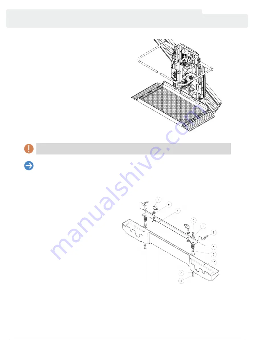
4.2.4
Frame Crush-Proofing
To mount the crush-proofing move the machine
from low stop.
Close the platform and access the lower part of
the frame.
Remove the self-supporting support.
With reference to figure, connect the support
(part 4) to the frame using the screws (part 9).
Fig. 37 - Crush-proofing device
Summary of Contents for RPSP
Page 1: ...Supra Linea Inclined Platform Lift Installation Manual INS RPSP EN 05 ...
Page 6: ...5 Installation Manual RPSP INS RPSP EN 05 Fig 2 General exploded view ...
Page 7: ...6 Installation Manual RPSP INS RPSP EN 05 Fig 3 Register exploded view ...
Page 8: ...7 Installation Manual RPSP INS RPSP EN 05 Fig 4 View of the guide ...
Page 9: ...8 Installation Manual RPSP INS RPSP EN 05 Fig 5 Machine body ...
Page 11: ...10 Installation Manual RPSP INS RPSP EN 05 Fig 7 Platform Fig 8 Lateral Motorized Flap SML ...
Page 12: ...11 Installation Manual RPSP INS RPSP EN 05 Fig 9 Frame crush proofing Fig 10 Anti impact ...
Page 14: ...13 Installation Manual RPSP INS RPSP EN 05 Fig 12 Three phase electrical motor connections ...
Page 57: ...56 Installation Manual RPSP INS RPSP EN 05 ...
Page 58: ...57 Installation Manual RPSP INS RPSP EN 05 ...
Page 60: ......