background image


WVD100 

Product Manual 

WVD100, Rev 2.5E 

Page 3 

EZ

  Loop 

Quick Start 

Overview: 

The EZ Loop is a wireless vehicle detector for vehicle use only.  

Each system can use one AP100 Access Point Relay Board 

mounted in the gate operator and up to ten S200 Sensors 

installed in the driveway. 

IMPORTANT:  Read the entire manual for complete and 

proper safety, installation and programming instructions. 
 

1.  Install The AP100: 

To install the AP100 Relay Board: 

1.  Mount the AP100 inside the gate operator or in a 

weather tight housing. 

2.  Mount the AP100 with a good line of sight to each 

sensor. 

3.  Use the plastic standoffs to mount the board.  Do 

not allow the board to rest on the ground or any 

metal. 


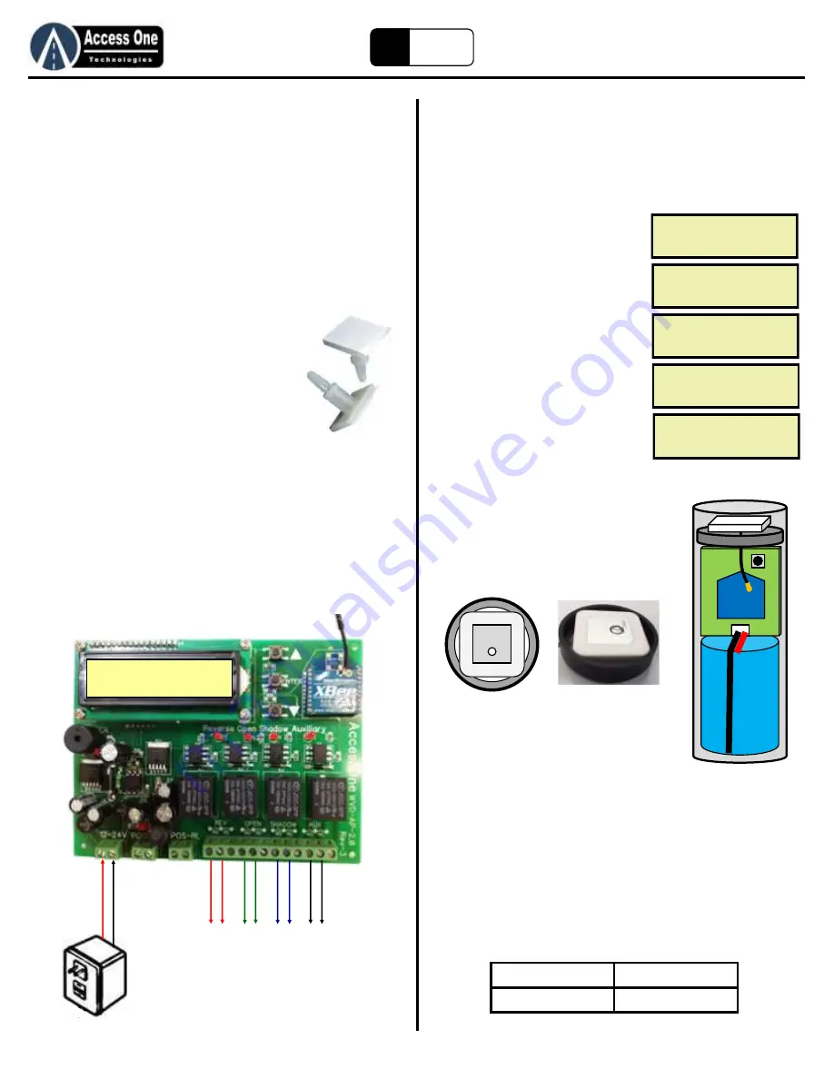
2.  Wiring The AP100: 

The AP100 has four relays for multiple loop functions.  Each relay 

has a NO, C, and NC output.  Most gate operators use the NO 

and C outputs. 

1.  Connect 12-24 VAC/VDC to the Power Terminal. 
2.  Connect Relay 1 to the Reverse Loop input.   
3.  Connect Relay 2 to the Open/Exit Loop input. 
4.  Connect Relay 3 to the Shadow Loop input. 
5.  Connect Relay 4 to an auxiliary device.  


Quick Start 

3.  Learn The Sensor: 

To learn the sensor before installing into the ground: 

1.  Make sure the AP100 is installed and power is on. 
2.  Open the Sensor, remove the circuit 

board,  and plug the battery on to the 

board. 

3.  Move the Sensor near the AP100 
4.  Enter the LEARN mode on the AP100 

Relay board: 
a.  Select PROGRAM, press Enter 
b.  Select SENSOR, press Enter 
c.  Select LEARN, press Enter 
d.  AP100 will display SEARCHING 
e.  Press the Sensor  learn button 
f.  AP100 will see the sensor and 

display SENSOR# EXISTS message 

g.  Press and hold the Enter button to 

exit programming 

5.  Mark the sensor number on each 

sensor  to identify them in setup. 

6.  Assemble the sensor with the battery, 

circuit board, antenna ring, and then 

antenna on top.  Make sure the 

antenna ring is under the antenna with 

the lip holding the square antenna.  

Gently fold the antenna wire without 

kinking it into the housing.   


4.  Program Relays: 

To program the relays to each sensor: 

1.  Program the relay function on the AP100: 

a.  Select PROGRAM, press Enter 
b.  Select SENSOR, press Enter 
c.  Select RELAY, press Enter 
d.  Select the Sensor to edit, press Enter 
e.  Select Relay for that sensor, press Enter 
f.  Select Relay Function, press Enter (NORMAL is the most common 

setting and will hold the relay while a vehicle is on the sensor, and 

drop the relay right after the vehicle leaves.) 

g.  Use Up, Down, Enter buttons to enter time of relay action for 

needed settings, press Enter 


ACCESS 

STATUS   

ONE 

PROGRAM -> 

PROGRAM  SENSOR 


AP 

SENSOR 

LEARN 


RELAY 

SEARCHING 

ENTER TO BACK 

SENSOR1 

EXISTS 


Relay 1 = Reverse 

Relay 3 = Shadow 

Relay 2 = Open 

Relay 4 = Auxiliary 

12V
-2

4AC

/D

R

ev

erse
 L

oo

G

at

e In
pu

O

pe

n/

Exi

t L

oo

Gat
e In
pu

Sh

ad

ow

 L

oo

G

at

e In
pu

Au

xi

liar

y D

ev

ice


(K

ey

pa

d,

 C

am
era

Summary of Contents for WVD100

Page 1: ...d qualified personnel for assistance DO NOT install this device unless all entrapment and pinch points are eliminated EZ Loop 1 Revision 2 5E WVD100 Wireless Vehicle Detector ACCESS STATUS ONE PROGRAM...

Page 2: ...Dirt or Gravel 11 Installing The S200P Sensor On A Hill 11 Installing The S200P Sensor In Snow 12 Above Ground Cap 12 Assemble the S200P Sensor 13 S600SM Learn Button 13 Assemble the S600SM Sensor 13...

Page 3: ...Move the Sensor near the AP100 4 Enter the LEARN mode on the AP100 Relay board a Select PROGRAM press Enter b Select SENSOR press Enter c Select LEARN press Enter d AP100 will display SEARCHING e Pre...

Page 4: ...detect a vehicle 4 Place the sensor far enough away from the gate so the moving gate does not activate the sensor Usually 8 10 feet from the gate Quick Start 7 Drill Sensor Hole To prepare the Sensor...

Page 5: ...potential hazards and pinch points have been eliminated Safety Information Restrictions and Limitations Please read and follow all restrictions and understand all limitations Do not install this produ...

Page 6: ...to any existing S200P sensor at any time Distance Chart Refer to the below chart for average distances for the sensor placement from the AP100 antenna Installation Mounting The AP100 The AP100 Relay...

Page 7: ...tenna Line of Sight Because significant signal strength is lost when a sensor is placed in the hole it is very important to install the antenna in a location with a full clear line of sight to every s...

Page 8: ...r 2 4 feet total depth This feature is used to reduce false triggers and help to not pick up a slide gate after the vehicle has cleared Side detection is not reduced and is at full detection distance...

Page 9: ...This diagram is a basic layout and does not show safety devices pedestrian gate fencing etc Refer to the gate operator manual for proper details Most swing gate applications will use a Reverse Sensor...

Page 10: ...mine if one or multiple sensors will be needed for full detection across a wide traffic lane 3 Determine if one or multiple sensors will be needed to cover the detection area outside and inside the pa...

Page 11: ...P Sensor On A Hill Hill applications can be difficult for installation as the hill can create signal loss and require some adjustments to the sensor installation Because of the signal issues that can...

Page 12: ...recessed deep enough that a snow plow will not hit it Make sure to seal the cap so it does not move Screws or anchors are recommended for this application so future access for service is more simple...

Page 13: ...ch the Sensor board 3 Place the antenna face down in the antenna compartment with the antenna wire going through the slot to the Sensor board Green back of the antenna should be seen 4 Place the Senso...

Page 14: ...xy similar to what is used to hold down highway reflectors can be used One source we recommend is https stop painting com order_form asp Stop Painting com AP 43 Epoxy Kit for Road Reflectors One Quart...

Page 15: ...whatever function is desired Each Sensor can be set to activate a single relay or multiple relays and different relay functions can be set for each Sensor For example Sensor1 may be programmed to acti...

Page 16: ...ing then moved to install in its hole the sensor will detect and lock on detect until it is reset A sensor will reset automatically after 14 minutes At that time the sensor will retune itself to its n...

Page 17: ...used Default 100 1 Select PROGRAM press Enter 2 Select SENSOR press Enter 3 Select SENSE press Enter 4 Select SENSORx press Enter x Sensor being programmed 5 Select the X Y or Z setting press Enter 6...

Page 18: ...nking and turn on or off each time the Learn button is pressed Sensor Programming Sensor Park Fail Rev 2 5 CAUTION This is a preliminary feature and has not been fully tested and approved for use Use...

Page 19: ...rns the alarm on off and resets the Fault Status Log Default setting is On To change the setting or clear the Fault Status Log 1 Select PROGRAM press Enter 2 Select AP press Enter 3 Select ALARM press...

Page 20: ...ed when in detection mode For example a vehicle approaching the sensor straight on will not be detected until 1 2 feet from the sensor But when the sensor detects the vehicle it expands the depth to 2...

Page 21: ...nd screen a few seconds later Faults Status Fault status is a log of the last ten faults It tracks the date time and sensor or controller that failed To view the fault log 1 Select STATUS press Enter...

Page 22: ...r1 1 Program the shared Sensor number ACTIVE 2 Delete the shared Sensor number 3 Reset the Sensors and relearn AP100 does not see Sensor detect 1 Make sure the Sensor has been programmed ACTIVE 2 Moun...

Page 23: ...Restrictions and Limitations set forth in this manual 2 A moving gate can cause serious injury or death Read and follow all installation manuals reference manuals and warning label instructions 3 Veh...

Page 24: ...www AccessOneTechnologies com...

Reviews: