background image

34

Technical Information

Step

Procedure

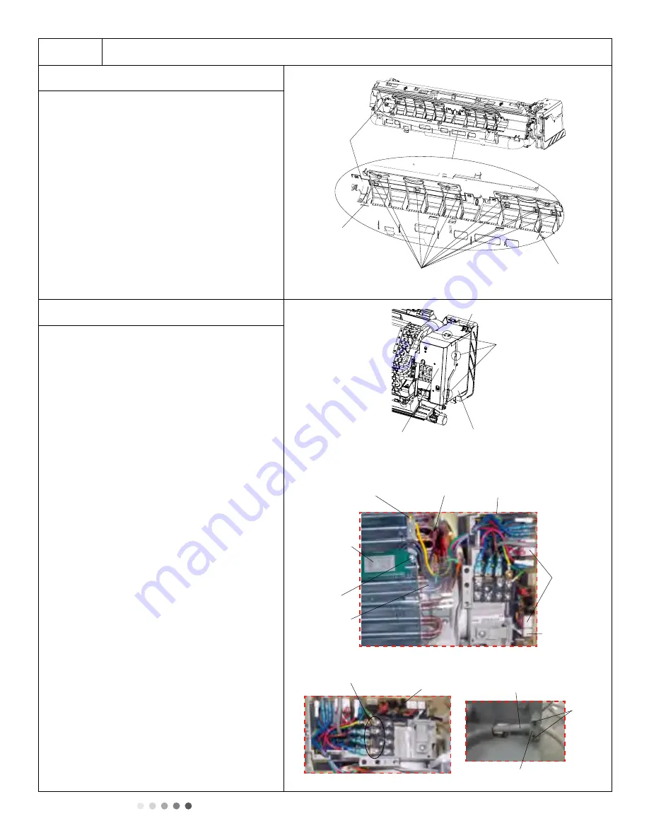
7.  Remove vertical louver

Loosen connection clasps between vertical 
louver and bottom case to remove vertical 
louver.

8. Remove electric box assy

a. Loosen connection clasps between shield

cover of electric box sub-assy and electric
box, then remove shield cover of electric
box sub-assy. Remove screw fixing
electric box assy .

b. Take off water retaining sheet. 

i. Remove cold plasma generator by 

unscrewing locking screw on generator.

ii. Take off indoor tube temperature sensor.
iii. Remove grounding screw.
iv. Remove wiring terminals of motor and

stepping motor.

v. Remove electric box assy.

c. Twist off screws that are locking each lead

wire and rotate the electric box assy.

Twist off screws that are locking the wire

clip. Loosen power cord and remove its
wiring terminal. Lift up the main board 
and remove it.

93

Installation and Maintenance

Service Manual

a

b

c

Procedure

Steps

Loosen the connection clasps between 
shield cover of electric box sub-assy and 
electric box, and then remove the shield 
cover of electric box sub-assy.
Remove the screw fixing electric box assy .

Take off the water retaining sheet.

Remove the cold plasma generator by
screwing off the locking screw on the

generator.

Take off the indoor tube temperature

sensor.

Screw off 1 grounding screw.

Remove the wiring terminals of motor and

stepping motor.

Remove the electric box assy.

Twist off the screws that are locking
each lead wire and rotate the electric

box assy.

Twist off the screws that are locking the
wire clip. Loosen the power cord and
remove its wiring terminal. Lift up the
main board and take it off.

8. Remove electric box assy

Electric box

Electric box assy

Clasps

S

hield cover of electric 

box sub-assy

Cold plasma
generator

Water retaining

sheet

Grounding screw

Screw

Power cord

Wire clip

Screws

Main board

Screw

Indoor tube
temperature 

sensor

Wiring
terminal
of motor

Wiring
terminal
of stepping
motor

Screw

Vertical 

louver

Vertical 

louver

Clasps 

Bottom 

case

Loosen the connection clasps between
vertical louver and bottom case to remove 
vertical louver.

7. Remove vertical louver

Summary of Contents for AWH09QB-A3DNA5K/O

Page 1: ...AC Pro 19 12k 115V A Series Service Manual Models AWH09QB A3DNB8K I AWH09QB A3DNA5K O AWH12QC A3DNB8K I AWH12QC A3DNA5K O Refrigerant R410A...

Page 2: ...We reserve the right to correct any clerical errors Copyright 2018 AC pro...

Page 3: ...5 Universal meter 6 Torque wrench open end wrench inner hexagon spanner 7 Electronic leakage detector 8 Vacuum pump 9 Pressure meter 10 Pipe pliers pipe cutter 11 Pipe expander pipe bender 12 Solderi...

Page 4: ...98 7 16 inch At least 5 7 8 inch At least 5 7 8 inch Space to the wall S p a c e t o t h e o b s t r u c t i o n r o o l f e h t o t e c a p S A t l e a s t 1 1 8 i n c h Space to the obstructio At le...

Page 5: ...it Bind up pipes and hang the indoor unit Install the support of outdoor unit select it according to the actual situation Fix outdoor unit Make the bound pipes pass through the wall hole and then conn...

Page 6: ...safety regulations use qualified power supply circuit and air switch c Make sure the power supply matches with the requirement of air conditioner Unstable power supply or incorrect wiring may result...

Page 7: ...4 51 32 55 31 4 Connect the Pipe of Indoor Unit a Aim the pipe joint at the corresponding bellmouth As show in Fig 5 b Pretightening the union nut with hand c Adjust the torque force by referring to...

Page 8: ...power and then separate the drain hose As show in Fig 15 3 Bind them evenly 4 The liquid pipe and gas pipe should be bound separately at the end 9 Hang the Indoor Unit 1 Put the bound pipes in the wa...

Page 9: ...d black brown brown black yellow green green yellow green green Screw Cable Cross Plate Sub assy Valve Cover U shaped curve Wall Drain hose Note The wiring connect is for reference only please refer t...

Page 10: ...aced in water 1 Use Vacuum Pump 1 Remove the valve caps on the liquid valve and gas valve and the nut of refrigerant charging vent 2 Connect the charging hose of piezometer to the refrigerant charging...

Page 11: ...t F4 4 5 Overload limit drop frequency F5 5 7 Over current limit drop frequency F6 6 3 High exhaust temperature limit drop frequency F8 8 1 Refrigerant leakage protection F9 9 2 Anti freezing limit dr...

Page 12: ...on diagnosis process Start End Is the wiring terminal between the temperature sensor and the controller loosened or poorly contacted Is there a short circuit due to trip over of the parts Replace the...

Page 13: ...oltage of this foot to neutral wire on the mainboard 53 enance s the control terminal of PG motor connected tightly s the feedback interface of PG motor connected tightly otor can t operate is broken...

Page 14: ...n and Mainten 3 Malfunction of Protection of Jumper Cap C5 Main detection points Is there jumper cap on the mainboard Is the jumper cap inserted correctly and tightly The jumper is broken The motor is...

Page 15: ...e IDU Fan Motor U8 Main detection points Instant energization after de energization while the capacitor discharges slowly Is the zero cross detection circuit of the mainboard defined abnormal Malfunct...

Page 16: ...ctric box are correctly connected Correct connection Connect the line according to wiring diagram Malfunction eliminated NO Main board matches with display board Main board of IDU matches with that of...

Page 17: ...alfunction of detecting plate WIFI JF Start Check if the connection wire are correctly connected Replace the detecting plate with the same model Malfunction eliminated YES Replace the detecting plate...

Page 18: ...the AC voltage between terminal L and N on wiring board XT power supply Shut down the power and wait 20 minutes or use DC voltmeter to measure the voltage on the two ends of capacitor or until the vol...

Page 19: ...the connection in correct order Is the voltage input of the machine within normal range Use AC voltmeter to measure the voltage between terminal L and N on wiring board XT Is the compressor coil resi...

Page 20: ...structed by other objects which affect the heat exchange of indoor and outdoor unit 2 If the indoor and outdoor fans working normally 3 If the environment temperature is too high this will result in t...

Page 21: ...utdoor ambient temperature higher than 53 20 minutes after the complete unit is powered off Is heat dissipation of the indoor unit and outdoor unit abnormal Does the outdoor fan work normally Replace...

Page 22: ...r stopping enough Fault diagnosis process Power on the unit Is stop time of the compressor longer than 3 minutes Does startup fail Are the wires for the compressor connected correctly Is connection se...

Page 23: ...ressor connected correctly Is connection sequence right Is the connection made in clockwise direction Is fault is eliminated Replace the control panel AP1 Replace the compressor End YES YES Connect th...

Page 24: ...after the complete unit is powered off NO Is the terminal FA for the electronic expansion valve connected correctly Resistances between the first four pins close to the terminal hole and the fifth pin...

Page 25: ...it Is the resistance around zero Remove the PFC capacitor and measure resistance between the two terminals Disconnect the terminals for the reactor and measure the resistance between the two terminals...

Page 26: ...ure occurred Check wiring inside of the indoor and outdoor units Are wires broken Check the communication circuit of the outdoor unit The communication circuit is abnormal Replace the main board of th...

Page 27: ...stem Filth blockage ice plug greasy blockage cut off valve hasn t been opened completely Is the compressor running abnormally Is there an abnormal sound or oil leakage Is the temperature of the shell...

Page 28: ...and outdoor unit is improper Check whether the installation postion is proper according to installation requirement for air conditioner Adjust the installation position and install the rainproofing an...

Page 29: ...replace compressor Cylinder of compressor is blocked Compressor canot operate Repair or replace compressor 6 Air Conditioner is Leaking Possible Causes Discriminating Method Air conditioner Status Tro...

Page 30: ...nance 10 Exploded View and Parts List 10 1 Indoor Unit 29 28 27 30 2 4 9 10 7 12 13 15 16 17 18 19 20 21 22 23 25 26 8 1 3 5 11 14 24 6 6 31 The component picture is only for reference please refer to...

Page 31: ...200004407 0100297601 1 13 Wall Mounting Frame 01252043 01252484 1 14 Cross Flow Fan 10352059 10352056 1 15 Fan Motor 1501208902 1501214605 1 16 Connecting Pipe Clamp 2611216401 2611216401 1 17 Drainag...

Page 32: ...for reference please refer to the actual product Service Manual 12 13 14 11 1 2 4 6 7 8 9 10 18 15 16 17 33 19 22 21 20 25 24 26 3 23 5 28 27 29 31 30 32 34 AWH12QC A3DNA5K O AWH09QB A3DNA5K O The co...

Page 33: ...100005 1 15 Valve Support 01713041 01713041 1 16 Valve 07100003 1 17 Cable Cross Plate sub assy 02123015 02123015 1 18 Cover of pass wire 01413069 01413069 1 19 Magnet Coil 4300040021 4300040021 1 20...

Page 34: ...nt panel Panel rotation Groove 91 Installation and Maintenance 11 1 Removal Procedure of Indoor Unit after turning off all power supplies and discharge the refrigerant completely before removal a b Ax...

Page 35: ...ecting plate WIFI Installation and Maintenance Service Manual a b Remove the screws fixing front case Note 1 Open the screw caps before removing the screws around the air outlet 2 The quantity of scre...

Page 36: ...inal Lift up the main board and take it off 8 Remove electric box assy Electric box Electric box assy Clasps Shield cover of electric box sub assy Cold plasma generator Water retaining sheet Grounding...

Page 37: ...then pull the terminal Circlip Soft sheath Holder Connector Procedure Steps Remove 3 screws fixing evaporator assy 9 Remove evaporator assy Screws Connection pipe clamp Evaporator assy Evaporator assy...

Page 38: ...ve screw fixing step motor then remove step motor Service Manual Procedure Steps Remove the screws fixing motor clamp and then remove the motor clamp Remove the screws at the connection place of cross...

Page 39: ...A3DNA6E O for example 96 Installation and Maintenance 11 2 Removal Procedure of Outdoor Unit Procedure Steps 1 Remove cable cross plate sub assy and valve cover 3 Remove front grille 2 Remove top cov...

Page 40: ...the valve support and the electric box Then remove the right side plate front panel right side plate 97 nstallation and Maintenance 4 Remove front panel 5 Remove right side plate 6 Remove axial flow b...

Page 41: ...ard sub assy to remove motor motor support electric box assy clapboard sub assy 98 Installation and Maintenance Service Manual 7 Remove motor and motor support 8 Remove electric box assy 9 Remove clap...

Page 42: ...rthe 4 weld spots connecting the 4 way Valve Assy to take it out Note Refrig erant shouldbe discharged firstly Welding processshould be as quickly as possible and keepwrapping cotton wet all the time...

Reviews: