System operation
13
System operation
General information
The device can be controlled as follows:
•
Using the remote control
•
Using the USB mouse
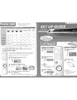
Operating elements on the device
Note
Pay attention to the overview on page 3.
No.
Name
Function
1
USB port
•
To connect a USB mouse
•
To connect a USB stick for data backups
2
Power LED
Lights up blue when the system is switched on
3
IR receiver
For the remote control
4
REC LED
Lights up red during recording
5
HDD LED
Flashes blue when the HDD is accessed
6
Network LED
Lights up red when the network is accessed
7
Alarm LED
Lights up red in the event of an alarm
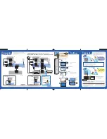
Connections on the rear of the device
Note
Pay attention to the overview on page 3.
No.
Name
Function
8
VIDEO IN:
BNC inputs
9
VIDEO OUT 1:
BNC monitor output
VIDEO OUT 2:
BNC spot monitor output
10
AUDIO IN:
Cinch audio input
11
LINE IN:
Cinch audio input for network transmis-
sion only (Audio will not be recorded)
12
AUDIO OUT:
Cinch audio output
13
LAN:
10/100 MBit Ethernet LAN connection
14
VGA:
VGA monitor output
15
USB port
•
To connect a USB mouse
•
To connect a USB stick for data backups
16
ALARM IN:
•
Alarm input 1–4
•
G = Ground
ALARM OUT:
•
Relay output and ground
RS-485:
•
Connection for PTZ cameras
17
RS-232: No function
18
12 V DC power socket
19
Power switch and mains power connection:
•
100–240 V AC, 50–60 Hz
20
Connection for earthing line