


Playback view
19
(4) Activate the e-PTZ function (depends on camera)
(5)
Activate audio for selected camera (red frame)
and adjust the volume
(6) Download the recorded data from the recorder
(7)
Activate full-screen mode for the active camera
(red frame
– exit with ESC)
Export functions
If snapshots or video clips are created from running play-
back, this data is stored in the user-specified directory on
your PC. You can manually change this path in the web
interface settings.
The default path for exported files is:
C:\Users\[USERNAME]\Web\
[USERNAME] is the name of the Windows user under
which the web interface is run.
Note
You can freely change the settings for the export
path under "Settings
→
Local".
Download
A new window opens when the download function is acti-
vated on the action bar. You can download the stored
video data from the recorder hard disk drive directly to
your PC from here. Select one or more files and click the
"Download" button to start the data transfer.
Under the default setting, continuous recordings are
stored in 1 GB blocks on the recorder. If the scene you
wish to access is in one of these blocks, the entire file
must be downloaded. Event recordings are stored in
smaller blocks (corresponding to the duration of the event
in question).
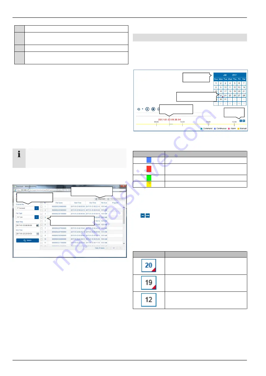
Using the timeline and calendar
The most important control element on the timeline is the
time tracker
. The time tracker indicates the current time
of playback. Move the timeline with the mouse using the
drag and drop function to change the playback time.
The recordings are displayed as coloured bars on the
timeline. The colour coding is explained below:
The default setting for the timeline display is 24 hours.
This means that recordings for the entire day are dis-
played. The timeline can be made smaller or larger using
the
button, in order to play back targeted time
ranges in the current day.
The days are selected using the
calendar
. The colour
coding for calendar days is explained below:
Colour
Meaning
Continuous recording
Event recording (motion, alarm input,
VCA)
Command (not currently in use)
Manual recording
Colour
Meaning
Currently selected day (blue text). The
current day has at least one recording
(red corner).
Day is not selected (black text), but
does have at least one recording (red
corner).
Day is not selected and has no record-
ings.
Time tracker
Zoom
Recordings
Select data
Define filters
Start download
Calendar


