background image

Live cast 


15 


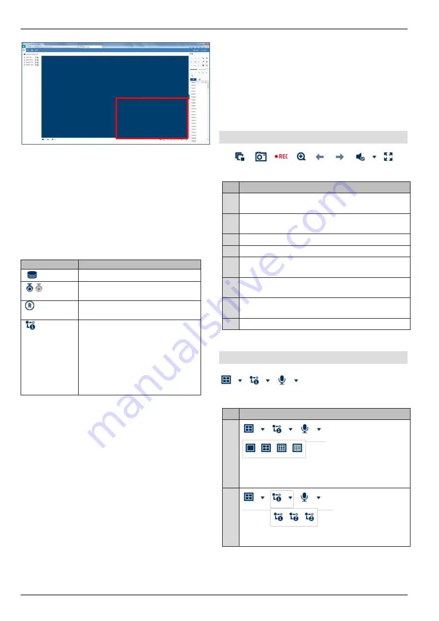
To display the camera at a specific position in the live im-
age (multi-view), proceed as follows: 


1.  Select the position in the live cast (red frame). 

2.  Double-click the desired camera in the camera 

list. 

3.  The camera is displayed at the desired position. 


The following functions/status displays are available in 
the camera list:  


The default setting for manual stream selection is "1". 
This means that the high-resolution "main stream" of the 
camera is displayed. This is the best option in most 
cases. It is only practical to adjust the manual stream se-
lection if there is a risk of a performance bottleneck dur-
ing transmission: 


If you wish to display lots of cameras at the same 
time (nine or more), the processing power of your 
PC may not be sufficient to decode all video 
streams. Change the setting to sub-stream "2". 


If you are accessing the web interface via the in-
ternet and wish to display multiple cameras at the 
same time, the upload of the receiving point must 
be of a sufficient size. At the same time, the 
download on the receiver side must also provide 
sufficient bandwidth. Change the setting to sub-

stream "2" if one of the two sides does not have 
enough bandwidth. 


If you are intentionally accessing the recorder via 
the internet with very low bandwidth, you can ac-
tivate transcoded stream "3" to request an image 
transfer with very low resolution and bit rate (e.g. 
QCIF/64 Kbit). The selected video stream is then 
scaled down by the recorder. 

Using the action bar 


        (1)      (2)      (3)     (4)     (5)     (6)        (7)      (8)  

No.   Meaning of the symbol 

(1) 

Stop all active camera live streams. Start all cam-
era live streams at the same time. 

(2) 

Create a snapshot of the selected camera (red 
frame) 

(3)  Create a manual data export (video clip) 

(4)  Activate the e-PTZ function (depends on camera) 

(5) 

Previous live cast view (function depends on se-
lected view 1x1, 2x2, 3x3, etc.) 

(6) 

Next live cast view (function depends on selected 
view 1x1, 2x2, 3x3, etc.) 

(7) 

Activate audio for selected camera (red frame) 
and adjust the volume 

(8)  Activate full-screen mode (exit with ESC) 


Using the view bar 


  (1)         (2)         (3) 
 

No.   Meaning of the symbol 

(1) 


Configure the live cast panel distribution (number 
of cameras which can displayed at the same 
time). 

(2) 


Select the live cast stream type to be used for all 
cameras simultaneously. 

Parameter 

Description 


Displays the recorder name 


Live cast display for camera is ac-
tive (blue) or deactivated (grey) 


Create a manual data export 
(video clip) 


Manually select the video stream 
of the desired camera. Hover the 
mouse cursor over the symbol to 
select the desired stream. The 
configuration for main/sub/trans-
coded streams can be adjusted in 
the settings under "Audio & video" 
in the "Stream type" section.  


Summary of Contents for NVR10010

Page 1: ...ABUS embedded NVR Web interface user manual Date 19 12 2019 Firmware 4 x x...

Page 2: ...art ing operation and using the device Make sure that this user manual is handed over when the product is given to other persons Keep this user manual to consult later You will find a list of contents...

Page 3: ...g up port forwarding IPv4 10 Setting up the ABUS server IPv4 11 DDNS for IPv6 IPv6 11 Access to DS Lite connections IPv6 11 Logging in for the first time 12 Live cast 14 General information on live im...

Page 4: ...ion on system 24 System settings 24 Overview 24 Time settings 24 Output menu 25 Maintenance 25 Upgrade and maintenance 25 Protocol 25 Camera management 25 Add manually 25 Quick add 26 Custom protocol...

Page 5: ...lance Note Data storage is subject to national data privacy guidelines When carrying out the installation advise your cus tomers of the existence of these guidelines General Before using this recorder...

Page 6: ...ion of conformity can be obtained from ABUS Security Center GmbH Co KG Linker Kreuthweg 5 86444 Affing GERMANY To ensure this condition is maintained and that safe oper ation is guaranteed it is your...

Page 7: ...cordings is only possible with the plug in installed Compatible recorders Device type Item number NVR NVR10010 NVR10020 NVR10030 NVR10040 NVR10050 NVR10020P NVR10030P Compatible browsers OS Browser Ve...

Page 8: ...idual cameras in the live image to facilitate this This approach reduces the bandwidth and requires less processing power for decryption on the PC In playback view the cameras are played back in the c...

Page 9: ...s of your recorder in order to access it via the local network Local interface Open the overview menu on the recorder s local interface and note the IP address ABUS IP installer Install the ABUS IP in...

Page 10: ...he intended receiving points to take potential limitations and instructions for the operation of the recorder into account ahead of time We provide the following tips and instructions for setting up e...

Page 11: ...up your recorder The ABUS server only supports IPv4 addresses Instructions on how to set up your recorder for the ABUS server are stored in the downloads area for the recorder on http www abus com DDN...

Page 12: ...ystem language If a notification for the plug in download appears this means that the recorder plug in is not yet installed on your PC and must first be downloaded and installed be fore you can procee...

Page 13: ...easily by scanning the QR code of the device This QR code is included in the scope of delivery or you can use the QR code displayed here in the menu Activate Tick the box to enable this service After...

Page 14: ...the menu bar The following options are available Using the camera list The camera list contains all cameras connected to the re corder Double clicking a camera name displays the cor responding camera...

Page 15: ...der via the internet with very low bandwidth you can ac tivate transcoded stream 3 to request an image transfer with very low resolution and bit rate e g QCIF 64 Kbit The selected video stream is then...

Page 16: ...aila ble 3D zoom zoom in out to a drawn screen Centring mode Speed Speed at which the cameras are man ually moved to positions Preset Navigate to tab to carry out preset positions Up to 256 present po...

Page 17: ...original view Playback function areas The playback view is divided into the following function areas Parameter Description Menu bar Global display of the configuration and control menus Archive list S...

Page 18: ...esult in a large upload for a remote connection Using the playback controls The playback controls are the core element of playback The basic functions for playing recorded data are pro vided here Usin...

Page 19: ...is in one of these blocks the entire file must be downloaded Event recordings are stored in smaller blocks corresponding to the duration of the event in question Using the timeline and calendar The mo...

Page 20: ...to narrow down the result list of image files Channel number camera selection File type event selection Start time End time The default path for exported files is C Users USERNAME Web USERNAME is the...

Page 21: ...s motion VCA I O etc Storage Menu for configuring recording pa rameters time schedules Vehicle Detec tion Configure Vehicle Detection settings VCA Configure VCA settings Note Some of the functions des...

Page 22: ...visual VCA rules in the live image and playback Image size The setting can force a specific image format for the live cast Fixed formats 4 3 16 9 may generate horizontal or vertical edges in the imag...

Page 23: ...e downloads Action Image clip settings Parameter Description Save snapshots in live cast to Path for storing snapshots from live cast Action Save snapshots during playback to Path for storing recordin...

Page 24: ...Time synchronisation via the network using the NTP server Important The NTP time does not recognise time zones so the time zone must be adjusted every time Server address URL host name of the NTP serv...

Page 25: ...targeted fil ter type Different parameters for Fil ter2 are available depending on the selection Filter2 Detailed filter depending on the Fil ter1 selection Start time Set the start time End time Set...

Page 26: ...automatically adding them Select one or more cameras in the Quick add dialogue using the button in the first column When you confirm with OK the recorder attempts to add these cameras as described abo...

Page 27: ...hen required if there is not enough infor mation on the path Typical layout of an RTSP streaming path rtsp 192 168 0 1 554 video h264 Parameter Setting Rtsp The protocol followed by 192 168 0 1 IP add...

Page 28: ...able Network settings DCHP IP address etc in correct Check and if necessary correct the network configuration Recording is not possible No HDD or HDD not initialised Install and initialise hard disk d...

Page 29: ...ABUS Embedded NVR Recorder Web interface user manual Manufacturer ABUS Security Center GmbH Co KG Linker Kreuthweg 5 86444 Affing Germany...

Reviews: