background image

11

12

8.  Hold the Sensor Inserter and firmly squeeze the 

2 blue release tabs at its base . Lift the Sensor 

Inserter straight up and away from the Sensor 

Support Mount . Be careful not to pull the Sensor 

Support Mount off of your skin during removal .
Note: 

Do NOT try to remove the Sensor Inserter 

without squeezing the blue release tabs as this may dislodge the Sensor 
Support Mount.

9.  After removing the Sensor Inserter, the Sensor is visible with its tip 

inserted into your skin and the top of the Sensor even with the top 

edge of the Sensor Support Mount . You may see a 

small amount of bleeding at the insertion site . If 

there is continuous bleeding that does not stop, 

remove the Sensor Support Mount and Sensor 

and repeat the Sensor insertion procedure with 

a new Sensor at a new insertion site .

10. Discard the Sensor Inserter safely . We recommend a 

sharps container or a puncture-proof container with a tight lid .

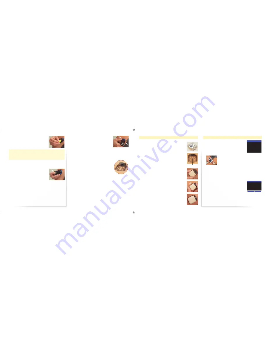
Attaching the Transmitter

Before attaching a new Transmitter to the Sensor 

Support Mount for the first time, write down the 

Transmitter serial number (located on the bottom 

surface of the Transmitter) .

Write down your serial number ________________

1.  After the Sensor has been inserted, position the 

Transmitter over the Sensor Support Mount so that 

the contact points face the Sensor .

2.  Lower the Transmitter onto the Sensor Support 

Mount directly over the round part of the “keyhole” .

3.  Hold the Transmitter between your index finger 

and thumb and slide the Transmitter until it clicks 

into place .
Note: 

Do NOT remove or replace the Transmitter from 

the Sensor Support Mount while wearing the Sensor. 
Doing so may end your Sensor life.

Keyhole

6.  Use your thumb and index finger to twist the 

locking pin, on top, one-quarter turn . Pull the 

locking pin to remove it .

CAUTION: Once the locking pin has been removed and the 

Insertion Buttons are pressed, a needle quickly goes just under 

your skin to place the Sensor . Do NOT press the buttons until you 

are ready to insert the Sensor .

7.  Hold the black part of the Sensor Inserter, avoiding the blue release 

tabs . Press down firmly on both grey Insertion Buttons on the top 

of the Sensor Inserter . Try not to press the Sensor Inserter assembly 

down into the skin when pressing the buttons . 

You may feel a slight pinch as the Sensor is 

placed under your skin .
Note: 

Both buttons must be fully depressed for the 

Sensor to be correctly inserted. The buttons are 
fully depressed when they are even with the top of 
the Sensor Inserter.

Connecting to a New Sensor

1.  On your Receiver, select Menu 

 Connect to 

Sensor . The Receiver instructs you to, “Hold 

Receiver next to Sensor .” Hold the Receiver next 

to the Transmitter/Sensor Unit . The Receiver 

searches for the wireless signal from the 

Transmitter .

When the Receiver connects with the Transmitter, 

the Receiver emits the Success tone (if Progress 

Tones are On) .


Note: 

If the Receiver cannot connect to the 

Transmitter, it notifies you with a screen message and 

the Failure tone (if Progress Tones are On). Check that the Transmitter is 
correctly attached to the Sensor Support Mount and that the Receiver is 
directly on top of the Transmitter. Press 

Yes

 to try connecting again.

2.  The first time you connect a new Transmitter to the Receiver a “New 

Transmitter Found” message is displayed on the screen .

•  Verify that the Transmitter ID displayed on 

the screen is the same as your Transmitter 

serial number that you wrote down 

(located on the bottom surface of the 

Transmitter) .

•  If this number does not match, press No .
•  If this number matches, press Yes to continue 

to the Sensor Code screen .

CONNECT TO SENSOR

Hold Receiver next to

Sensor.

Looking for Sensor...

CONNECT TO SENSOR

New Transmitter found.
Transmitter ID:
AADN219-D0046
Is this yours?

No

Yes

Only Displayed for  

New Transmitters

ART22683-101_rev-B.indd   11-12

1/7/15   11:43 AM

Summary of Contents for FreeStyle Navigator II

Page 1: ...Continuous Glucose Monitoring System User s Manual ART22683 101_rev B indd 1 1 7 15 11 43 AM ...

Page 2: ...ng Glucose Targets and Alarms 18 Glucose Targets 18 Glucose Alarms Settings 19 Glucose Alarms 20 Alarm Tones 20 Day Night Glucose Alarms 21 Audio Vibrate Settings 22 Mute Un Mute Alarms 22 Alarm Snooze Setup 23 Responding to Alarms 23 Troubleshooting 24 Living with Your FreeStyle Navigator II System 24 Reconnecting to a Sensor if Signal is Interrupted 24 Wireless Transmission Range 24 Bathing Show...

Page 3: ...inually measuring interstitial fluid glucose levels in people age 6 and older with diabetes mellitus The indication for children age 6 17 is limited to those who are supervised by a caregiver who is at least 18 years of age The caregiver is responsible for managing or assisting the child to manage the FreeStyle Navigator II System and also for interpreting or assisting the child to interpret FreeS...

Page 4: ...le use component that attaches to your skin with an adhesive pad Designed to hold the Transmitter and Sensor on your body for up to 5 days The combination of the Sensor Support Mount with Sensor and the Transmitter that is worn on your body is known as the Transmitter Sensor Unit System Related Information The FreeStyle Navigator II System is designed as a complete system Use only the FreeStyle Na...

Page 5: ... on display Temporarily mute an alarm Blood Glucose Meter Test Strip Port and Light USB Port Rotate wheel to scroll among menu options or data Press in to select menu options and to confirm edits ScrollWheel Reset Button Back Button Press and hold to return to Home screen Cancel selection Move to a previous screen without saving changes Note Pressure or force applied to the screen of the Receiver ...

Page 6: ...e may be shortened if you activate the display frequently The number of alarms you receive may also shorten battery life Upon disconnecting from the Charging Cable the Receiver completes a sequence of self checks If the display is turned on the Receiver emits tones vibrates and flashes screen checks during this time If the Receiver Charging Cable Receiver and A C Wall Charger can detect that any p...

Page 7: ...ld occur or the Sensor Support Mount may not stick to the site 2 Remove the Sensor Inserter and Sensor Support Mount from their sterile packages Save the package of the Sensor Inserter it contains the Sensor Code number You need to enter this code number into the Receiver at a later step Note Make note of the Sensor Code found on the Sensor Inserter packaging You will need to enter this code after...

Page 8: ...has been removed and the Insertion Buttons are pressed a needle quickly goes just under your skin to place the Sensor Do NOT press the buttons until you are ready to insert the Sensor 7 Hold the black part of the Sensor Inserter avoiding the blue release tabs Press down firmly on both grey Insertion Buttons on the top of the Sensor Inserter Try not to press the Sensor Inserter assembly down into t...

Page 9: ...r serial number the Sensor Code screen is displayed 4 Using the Scroll Wheel enter the 3 digit Sensor Code from the Sensor Inserter packaging CAUTION The code numbers MUST match to ensure accurate glucose results Note Once the Sensor Code has been entered and you have pressed Accept you cannot change the Sensor Code number Be careful If you enter the code incorrectly you have to replace the Sensor...

Page 10: ...rglycaemia GLUCOSE READING Control Solution No Home Low GLUCOSE READING Control Solution No Home High Notes Use a new sterile lancet each time NEVER use a lancet or lancing device for more than one person Follow instructions for your lancing device Apply blood sample and wait for results 1 Gently apply blood to ONLY ONE sample area of the test strip Only a very tiny drop of blood is needed Note Do...

Page 11: ...ting the Transmitter within approximately 1 minute you may get a screen which reads TX DETACHED Transmitter has detached from Sensor CGM is not available Replace the Sensor to continue CGM If this screen is displayed press OK If you don t separate the Transmitter from the Sensor Support Mount the Receiver displays a screen which reads Did you remove the Sensor Select Yes to end CGM Press Yes 3 Dis...

Page 12: ...Data Loss System Beep Pulse Harp Zing Delight Rhythm Vibe vibrate Off Note Exercise caution when turning off alarms For example if you turn off the Low Glucose Alarms you do NOT receive text audible nor vibratory notification for low glucose events Glucose Alarms Settings Type What It Is Settings Available OK LOW GLUCOSE Low glucose below 75 mg dL 74mg dL The low glucose alarm notifies you when yo...

Page 13: ...s for more than 12 hours you must select Menu Alarms Tones and turn off alarms one at a time Day Night Glucose Alarms GLUCOSE ALARMS Night Start 21 00 Day Start 07 00 Next Menu Alarms Glucose Alarms Glucose Alarms Options Comments Day Start 00 00 24 00 Day and Night Alarm settings allow you to define different glucose alarm thresholds for different times of the day Night Start 00 00 24 00 Day and ...

Page 14: ... wide variety of indoor and outdoor activities Depending on the activity there are some considerations to be aware of Alarm Snooze Setup The FreeStyle Navigator II System includes a Low Glucose Snooze and High Glucose Snooze feature that allows you to set how frequently a Low Glucose or High Glucose Alarm repeats after you have already cleared the alarm Accept SNOOZE SETUP Low Glucose 30 min High ...

Page 15: ... 2 Wash the skin in mild soap and water and dry thoroughly 3 Check to make sure the inside of the skin is completely dry before putting it back on the Receiver Travelling Check with local authorities prior to departure as rules and regulations may change without notice Follow these guidelines when travelling Notify security personnel of the presence of the device when going through security system...

Page 16: ...000 feet Operating Pressure 1 0 bar 14 7 psia sea level to 0 7 bar 10 1 psia 3 048 metres 10 000 feet Sensor Life Up to 5 days Sensor Operating Skin Surface Temperature 25 ºC to 40 ºC 77 ºF to 104 ºF Glucose Result Range 20 to 500 mg dL 1 1 to 27 8 mmol L Receiver Memory 60 days of normal use including continuous glucose readings stored every 10 minutes and daily blood glucose readings Transmitter...

Page 17: ...y charge An icon without a plug indicates that the battery is not currently being charged Charging An icon with a plug indicates the battery is charging Charged If the entire icon is green this indicates the Receiver is completely charged Audio Vibrate Audio and Vibrate The audio and vibratory settings for your Receiver The settings apply to glucose data loss and system alarms but not to your Prog...

Page 18: ...facturer s declaration electromagnetic immunity The System is intended for use in the electromagnetic environment specified below The customer or the user of the System should assure that it is used in such an environment IMMUNITY test IEC 60601 test level Compliance Level Electromagnetic environment guidance Electrostatic discharge ESD IEC 61000 4 2 6 kV contact 8 kV air 6 kV contact 8 kV air Flo...

Page 19: ... by an electromagnetic site survey a should be less than the compliance level in each frequency range b Interference may occur in the vicinity of equipment marked with the following symbol NOTE 1 At 80 MHz and 800 MHz the higher frequency range applies NOTE 2 These guidelines may not apply in all situations Electromagnetic propagation is affected by absorption and reflection from structures object...

Page 20: ...o frequency of transmitter m 150 kHz to 80 MHz 1 2 d 80 MHz to 800 MHz 1 2 d 800 MHz to 2 5 GHz 2 3 d 0 01 0 12 0 12 0 23 0 1 0 38 0 38 0 73 1 1 2 1 2 2 3 10 3 8 3 8 7 3 100 12 12 23 For transmitters rated at a maximum output power not listed above the recommended separation distance d in metres m can be estimated using the equation applicable to the frequency of the transmitter where P is the max...

Page 21: ...Abbott Diabetes Care Inc 1360 South Loop Road Alameda CA 94502 USA PRT22683 101 in various jurisdictions 2011 2013 ART22683 101 Rev B 01 15 ART22683 101_rev B indd 37 1 7 15 11 43 AM ...

Reviews: