10
Zenith Automatic Transfer Switch | new.abb.com/low-voltage
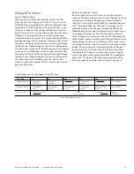
Power Cable Access Location
Power cables can be accessed from the rear or side by removing panel screws carefully. While installing the units keep adequate
space in the sides & rear of the unit for ease of accessing the power cables. It is recommended not to stand on any of the
components while accessing the power cables.
Section 4: Standalone ATS Product Operation
controller & enclosures. Refer the electrical schematic diagram provided for the electrical connections. Follow all the warning
& caution instructions before energizing the unit. Operate the switch manually before making the electrical connections.
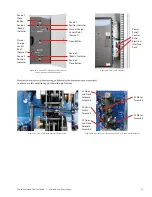
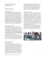
Removable
Side and
Rear Covers
Removable
Side Covers
for Cable
and
Interlocking
Access
Removable Rear Covers for Cable Access
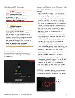
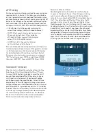
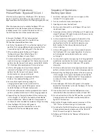
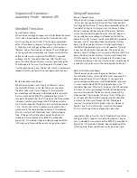
Options Panel
ATS Mechanical
Indicator Panel
MX Controller HMI
Control Switch
Options Panel
Access Panel
Electrical Panel
Fiscia
Options Panel
(on request)
Figure S3-6 : Standalone ATS –NEMA1 Enclosure Front Iso view
Figure S3-7 : Bypass Isolation ATS NEMA1 Enclosure Rear Iso view
Figure S4-1: Front view of ATS (Standalone) in an enclosure (MX350 variant).
Figure S4-2: Front view of ATS (Standalone) in an enclosure (MX350 variant).

