29
Zenith Automatic Transfer Switch | new.abb.com/low-voltage
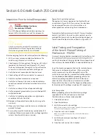
7. Start the generator’s engine.
NOTE: The controller will illuminate Source 2 Available LED when preset voltage
and frequency levels are reached.
8. Verify the phase to phase voltages at Source 1
line terminals.
9. Verify that the phase rotation of Source 1 is the same as
the phase rotation of Source 2.
10. Shut down the generator’s engine.
11. Place the starting control in the Automatic position.
12. Complete the visual inspection of the transfer switch.
13. Close the enclosure
TRANSFER AND BYPASS ISOLATION SWITCH
Order Number:
Equipment ID:
Serial Number:
RATING
Volts: Voltage
Hz:Hz
Amps: Amps
Phase: Phase
U.S. PATENT. WWW.GECRITICALPOWERPATENTS.COM
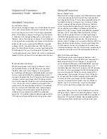
follow these steps to set up the ATS. The annunciation LEDs
illuminate to indicate (1) source availability, (2) ATS position,
and (3) Entelli- Switch 250 control function (timing).
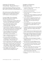
Figure S6-1: Label on Fascia containing product serial number and voltage rating.
Figure S6-2: Entelli-Switch 250 front display.
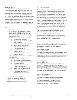
1. Unlock the enclosure.
2. Open the enclosure.
3. Place the Control Switch in the Inhibit.
4. Close the external (up-stream) Source 1 circuit breaker.
NOTES: Source 1 Available and Source 1 Position LED’s will illuminate. If Source
1 Available LED does not illuminate, verify that Source 1 Voltage is above the
preset restore value. The Gen-Set will start and run
while Source 2 stop Delay Timer is timing.
5. Close the External (up-stream) Source 2 line circuit breaker.
6. Start the engine generator in MANUAL mode.
NOTE: When the voltage and frequency reach preset values, the Source 2
Available LED will illuminate.
7. Verify the phase to phase voltages at Source 2
line terminals.
8. Verify that the phase rotation of Source 2 is the same as
the phase rotation of Source 1.
9. Shut down the generator’s engine.
(Place in Automatic Mode.)
NOTE: Source 2 Available LED will turn off.
NOTE: The engine generator will continue to run for the duration of Source 2
Stop Delay Timer.
10. Place the Control Switch to Inhibit.
11. Complete the visual inspection of the transfer switch.
12. Close the enclosure.
13. Lock the enclosure.

