


9 Commissioning
73
9.2.3 Mounting of the External Drive Shafts
The external drive shafts consists of square tubes and shall be connected to the
spherical shaft ends on bevel gears and motor-drive mechanism by means of two
coupling halves.
CAUTION
Before mounting of shafts and couplings, everything must be cleaned and greased for
correct function.
Apply a thin layer of grease, GULF-718EP Synthetic grease or Mobilgrease 28 or
SHELL-Aero Shell Grease 22 to all spherical shaft ends and unpainted surfaces of the
bevel gears.
NOTE:
The multihole coupling should be greased.
NOTE:
The tubes around shafts and couplings are for protection.
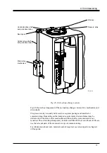
The arrangement of the driving shaft system is shown in Fig. 40.
CAUTION
Make sure that all locking devices (on the bevel gear, on the on-load tap-changer and
in the motor drive) are mounted and the on-load tap-changer and the motor-drive are
in the same service position.
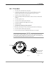
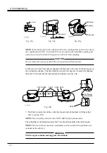
Check that the motor-drive mechanism is in its exact position according to Fig. 39. The
red mark on the brake disc facing the red mark on the brake assembly. If not, loosen the
locking device and adjust it to its exact position. Remount the locking device.
9.2.4 Mounting of the Vertical Drive Shaft
1. Mount the bevel gear SA21 on the transformer with O-ring, SA20, clamps SA17
screws and washers, see Figs. 49b and 49d.
2. Put the square shaft SA14 with protective tubes SA15 and SA16 and hose clips
according to Fig. 49a. Connect the square shaft with the mounted coupling halves
to the motor-drive. Mount two coupling halves SA11 to the other end of the square
shaft and the shaft of the bevel gear, see Fig. 49b. Push the shaft to the bottom of
the fitting in the coupling halves, see Fig. 50e. Tighten the screws lightly and
check that the shaft can be moved approximately 2 mm in axial direction (axial
play). Check the dimension shown in Fig. 50f. Tighten the screws A first and
thereafter the other, see Fig. 50d.
3. Mount the protective tube with the greater diameter, SA16 to the bevel gear with a
hose clip, and the other tube SA15 to the flange of the motor-drive mechanism,
see Fig. 49c. Leave about 3 mm play to the flange ring, see Fig. 49e, for water
draining.


