


26
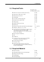
3 Installation in the Transformer
3.1.3 UCD with Tap Selector size G
1. Unpack the diverter switch housing and the tap selector. Remove the drying
agents and the yellow cushions with vapour phase inhibitor for protection against
corrosion in the tap selector and on the diverter switch housing.
2. Fit the gasket into the on-load tap-changer flange on the transformer cover, see
Fig. 5 (This gasket is not included in the delivery).
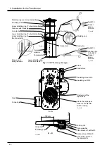
3. When the impulse withstand voltage to earth exceeds 380 kV, the on-load tap-
changer is provided with shielding rings. Before mounting the diverter switch
housing on the transformer cover the lower shielding ring must be dismantled, see
Fig. 17.
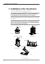
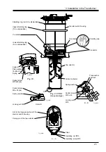
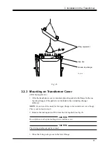
4. Lift the diverter switch housing in the lifting eyes as shown in Fig. 3 and lower it
carefully through the opening in the transformer top cover, see Fig. 4. Place the
diverter switch housing correctly in position for mounting the outer shaft system
(see transformer drawing). The studs on the flange on the transformer cover shall
fit into the flange of the diverter switch housing. Mount thirty washers and M16
nuts, see Fig. 5. Tighten the nuts.
5. If the impulse withstand voltage to earth exceeds 380 kV, mount the dismantled
shielding ring on the diverter switch housing, see Fig. 17.
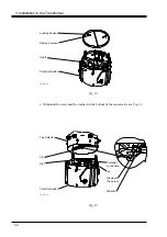
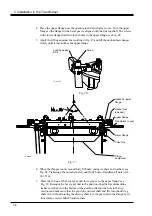
6. Put the tap selector in position for joining to the diverter switch housing. Lift in
the lifting eyes as shown in Fig. 3.
In case the on-load tap-changer is equipped with a tie-in resistor for mounting
under the tap selector, the tie-in resistor is mounted after joining the tap selector to
the diverter switch housing. After mounting the tie-in resistor, the on-load tap-
changer must not be put down standing on the tie-in resistor. It must be hanging,
for instance in a traverse.
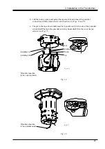
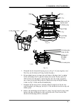
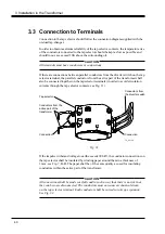
7. Remove the transport locking and the lifting eyes with fasteners from the top
section of the tap selector, see Fig. 11.
CAUTION
Do not operate the tap selector until it is connected to the diverter switch housing.
TC_00183
Lifting eyes with
fasterens (to be
removed)
Transport locking
(to be removed)
Screws (to be
removed)
Max 90
o
Screws (to be
removed)
Fig. 11.


