


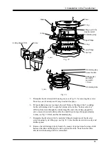


9. Loosening the screws for the four clamps that keep the bevel gear and remove the
bevel gear. Take care of O-ring, clamps and fasteners. Store the bevel gear in a
dust-free place.
CAUTION
Do not remove the locking device of the bevel gear.
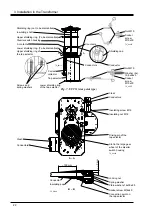
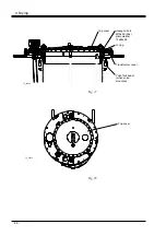
10. Mount the locking device DS 4 on the driving shaft of the on-load tap-changer,
see Fig. 23.
CAUTION
The driving shaft must not be rotated.
11. Remove the nuts and washers inside the upper flange and remove the flange by
lifting in the lifting eyes. Store the upper flange, its O-ring and fasteners in a dry
and dust-free place.
12. The on-load tap-changer is now ready for drying together with the transformer.
Follow instructions in chapter 4.
3.2.2 Mounting when the Transformer Ratio
Measurement is carried out after Drying
1. Assemble the diverter switch housing and the tap selector as follows:
UCC with tap selector IV, section 3.1.1, steps 1, 6-13
UCD with tap selector III, section 3.1.2, steps 1, 6-13
UCD with tap selector G, section 3.1.3, steps 1, 6-13
2. Follow instructions according to section 3.2.1, steps 5-12.
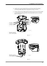
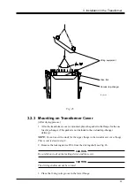
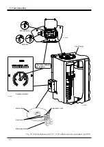
3. Apply the lifting equipment LL330 016-D in position according to Fig. 25.
NOTE:
The lifting equipment must be tilted when applying.
4. Lift the on-load tap-changer onto the yoke fork (use the lifting equipment
according to step 3). Place the on-load tap-changer correctly in position for
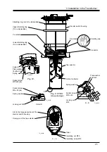
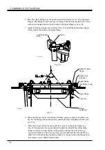
mounting the outer shaft system (see transformer drawing). Insert the supplied
guiding bolts DS 7, and insulating bushings (not included in delivery) in the lower
flange, see Fig. 21. The guiding bolts shall fit into the holes in the yoke fork and
be secured by punch marks in the pins. When the on-load tap-changer is in place,
remove the lifting equipment.
5. Mount the conductors between the transformer winding and the tap selector
according to section 3.3.
6. The on-load tap-changer is now ready for drying together with the transformer.
Follow the instructions in chapter 4.
36
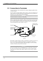
3 Installation in the Transformer


