


3 Installation in the Transformer
40
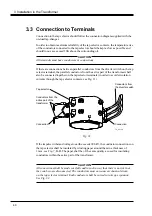
3.3 Connection to Terminals
Connection to the tap selector should follow the connection diagram supplied with the
on-load tap-changer.
In order to obtain maximum reliability of the tap selector contacts, the temperature rise
of the conductors connected to the tap selector should be kept as low as possible and
should in no case exceed 30K above the surrounding oil.
CAUTION
All terminals must have conductors or connections.
If there are connections between parallel conductors from the diverter switch on the tap
selector terminal, the parallel conductors from the active part of the transformer shall
also be connected together on the tap selector terminals (in order to avoid circulation
currents through the tap selector contacts, see Fig. 31).
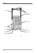
Connection
Conductors from the
active part of the
transformer
Tap selector
Conductors from
the diverter switch
Connection
Fig. 31.
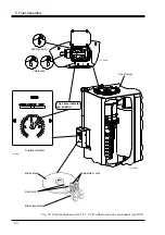
If the impulse withstand voltage to earth exceeds 380 kV, the conductor connections on
the tap selector shall be insulated by winding paper around them to a thickness of
3 mm, see Fig. 7, B-B. The paper shall be of the same quality as used for insulating
conductors within the active part of the transformer.
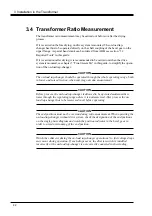
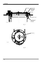
CAUTION
All connections shall be made carefully and in such a way that there is no risk that
they can become disconnected. The conductors must not cause mechanical strain
on the tap selector terminal. Each conductor shall be curved to take up expansion.
See Fig. 32.
TC_00130


