


Controlled Switching — Buyer´s Guide
N-
Edition 2, 2006-09
Quality, Testing and Commissioning
Technical Information
Quality, Testing and Commissioning
Commissioning
It is important to verify the overall functional
performance of complete, controlled switch-
ing systems after installation.
The purpose of commissioning tests is to
verify stable and intended results of the con-
trolled operations.
For controlled switching operations that are
performed in a non-adaptive mode, which
is the case for most controlled opening ap-
plications, the controller makes no check of
the results and tests are therefore needed
to verify the performance. Additionally, con-
trolled switching operations performed in
adaptive mode must be verified upon com-
missioning to ensure that the intended results
are attained. Even in adaptive mode, the
controller may, because of incorrect settings
or connections, display successful results
even though this may not be the case.
The recommended commissioning proce-
dures for different applications are given
below.
Switchsync™ E113, E213 and
F236
For controlled switching applications when
using Switchsync™ controllers E3, E23
and F236 (switching towards fixed targets)
the following should be recorded:
- Busbar voltages (or at least the reference
voltage)
- Load currents in each phase
- Output command(s) from the controller
The measured making instants can easily be
compared to the intended making targets
that are expressed as a certain phase shift
with respect to the busbar reference voltage.
For controlled opening, the output activation
instants are needed to check the contact
parting instants with respect to the phase
shift of the load currents. The output com-
mands together with the measured no-load
opening times are used for the determination
of contact separation instants. For opera-
tions performed in adaptive mode, read the
display after each operation and cross check
the displayed times against the recorded
switching times.
Quality and Testing
Circuit breakers and controllers are type- and
routine-tested according to applicable stan-
dards. The type tests are performed on rep-
resentative units while each device produced
is subjected to routine tests. Type- and rou-
tine tests are performed separately.
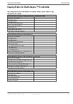
During routine testing, the controller function-
ality is tested under different conditions as
shown in the table below.
Circuit breaker dummies are used in the tests
to represent actual circuit breakers.
The following checks are made
during the routine tests:
Adjustments of detector circuits
Checking Watchdog and CRC-sum
Check of programming functionality on front
panel
Check of closing and opening operations
Check of line side voltage measurements and
residual flux measurements (L83 and T83
respectively)
Check of no operation while out of service
Check of behavior when reference voltage is lost
Check of behavior when multiple commands
are received
Check of adaptation control by means of cur-
rent start detection
Check of adaptation control by means of volt-
age onset detection
Check of performance in adaptive mode when
adaptation control signal is lost
Functionality check of compensation circuits
(F236, L83 and T83 only)
Check of behavior when supply voltage is lost
Check of performance when load side voltages
are inaccessible (L83 and T83 only)
Check of rapid action
Check of operation without adaptation control
Check of operating properties when pro-
grammed for one mechanism only
Check of PC-communication properties (F236,
L83 and T83 only)
As a final verification of the functional perfor-
mance of the complete controlled switching
system, it is advisable to follow the proposed
test procedure for commissioning tests de-
scribed in the next section.


