


Controlled Switching — Buyer´s Guide
H-
Edition 2, 2006-09
Adaptive Functions
Application
Adaptive Functions
Adaptation Control
All Switchsync
TM
controllers are equipped
with special functions to control the result of
a controlled switching operation.
The adaptation control can be arranged in
different ways and for both controlled closing
and controlled opening.
Deviations from the intended targets may be
caused by variations in the operating condi-
tions. The operating conditions that may
cause changes of the circuit breaker operat-
ing times are, for example, gradually increas-
ing contact burn-off caused by many switch-
ing operations, change of ambient tempera-
ture and variations of the auxiliary voltage.
The functioning principle of the adaptation
control is that a detected error from the tar-
get will be compensated for in the next con-
trolled operation.
If the circuit breaker should have a change
in operating time from the value assumed by
the Switchsync
TM
controller, then the adapta-
tion feedback signal from a sensor or trans-
ducer will appear either slightly later or earlier
than expected. When an error has been ob-
served by the controller, the internally created
waiting time will be modified for the next op-
eration in such a way that the circuit breaker
will be guided back to the intended target
Adaptation Control on Closing
Operations
The ultimate target for controlled closing is
the intended energizing instant. The optimum
way of supervising the energizing instant is
to note the phase angle at which the circuit
breaker starts to pre-strike with respect to
the selected reference.
This kind of control can easily be arranged
by receiving the current start signal(s), CUR-
RENT DETECTION, from a current trans-
former. As an alternative the voltage onset
instant(s) can be detected by means of a
voltage transformer behind the circuit break-
er, VOLTAGE DETECTION.
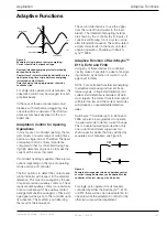
Figure 1.
Example of shunt capacitor bank energizing with
current start feedback loop.
A typical arrangement for detection of
current start is shown in Figure .
Note: A certain detection delay must be
taken into account if current start detec-
tion is used and when the current starts
sinusoidal (reactor energizing applica-
tions). The detection threshold depends
on the amplitude of the secondary cur-
rent.
It should also be noted that coupled
phases (for example YNd-transformers,
having a secondary delta winding) will
cause simultaneous voltage start in all
phases when only one pole has energized
its winding.
If no instrument transformers are avail-
able, it is still possible to supervise the
result of a controlled closing operation
by detecting the contact touch instant(s)
of the circuit breaker. In this application,
the VOLTAGE DETECTION function will
be used and the signal will be given by
a precision auxiliary contact. Note that
the contact touch instant differs from the
energizing instant by the pre-arcing time;
see Figure 2.
Busbar
Switchsync
Controller
Input
Command
Feedback
Signal
Output Command
Circuit
Breaker
Capacitor
Bank
VT


