


Controlled Switching — Buyer´s Guide
B-8
Edition 2, 2006-09
Explanations
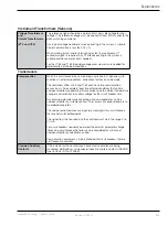
Circuit Breaker Characteristics cont.
Make Time
Time from energizing the closing coil until current starts to flow in the main
circuit. Adaptation control adjusts the making instant.
Pre-arcing Time
Time from start of current flow in the main circuit until contact touch.
Pre-arcing time = Closing time - Make time
Restrike
Voltage breakdown in the circuit breaker at a time equal to or exceeding a
quarter of a cycle after attempt to interrupt.
Reignition
Voltage breakdown in the circuit breaker within a quarter of a cycle from
attempt to interrupt.
Opening Time
Time from energizing the opening coil until contact separation occurs.
Arcing Time
Time from contact separation until current interruption.
Control Circuit Arrangements
Fault Clearance
Since a controlled opening operation will cause an extended clearing time
(input check duration, time for finding final reference point and additional
waiting time) it is important to arrange all fault tripping commands to by-
pass the controller.
Trip Circuit
Supervision
(TCS)
Close Circuit
Supervision (CCS)
Trip or Close Circuit Supervision can be arranged but must be installed in
the controller output circuit. No Close or Trip Circuit Supervision should be
installed in the controller input circuit.
System and Switching Conditions
Grounding of the Load
The type of grounding of the load is an important parameter for defining
the optimum targets for controlled switching. The grounding of the load
also defines the optimum mechanical staggering of the three-pole operated
circuit breakers.
Connection of Main
Circuit
A three-pole operated, mechanically staggered circuit breaker is not
symmetrical. Therefore in some applications, for most grounded loads,
it is very important that the recommended pole-phase connections are
followed. The principle is that intended making or breaking operations shall
take place in reverse phase order (i.e. order R-T-S in a network with positive
sequence voltages in order R-S-T).
Information about relevant alternative connections is available at ABB
Power Technologies, High Voltage Products, Ludvika, Sweden.
Trapped Charge
DC voltage left on a capacitor bank or uncompensated transmission line
after interruption.
Residual Flux
Remaining flux in the transformer core after de-energizing.
Phase designations
In a three-phase system the three phases may be named differently
depending on utility practices. Examples of some typical phase
designations are: A-B-C, R-S-T, R-Y-B, L-L2-L3 and 0-4-8.
All three-phase examples in this document are shown using the phase
designations R-S-T and with a phase rotation equal to R->S->T.


