


Controlled Switching — Buyer´s Guide
I-
Edition 2, 2006-09
Impact of Substation Configuration
Application
Impact of Substation Configuration
Substation Configurations
Generally, every circuit breaker to be con-
trolled will need its own controller. However,
in some substation configurations one cir-
cuit breaker may switch two different loads,
which may call for more than one controller
per circuit breaker.
In most cases, a specific load is switched by
its own circuit breaker. In some substation
configurations, one load may be alternatively
switched by different circuit breakers.
The following two conditions call for special
care.
- One load switched by two circuit breakers
- Two different loads alternatively switched by
the same circuit breaker
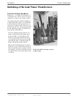
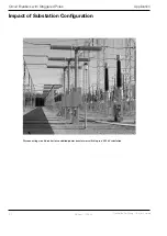
A typical example where special attention
is required is shown in Figure . The figure
shows a circuit breaker and a half substation
layout and two outgoing uncompensated
transmission lines:
Figure 1.
Circuit breaker and a half scheme in which one load
may be switched by two alternative circuit breakers,
but also where two different loads may be switched
by one circuit breaker.
The example shown above illustrates two
complexities. The first is that one circuit
breaker may switch two different loads. An-
other complexity is that one load may be
switched by two different circuit breakers.
To arrange for full operational flexibility in a
scheme as shown in the figure, circuit break-
er CB2 requires two controllers (B and C).
The source side reference when switching
in Line will be the line side voltage of Line
2. Furthermore, the line side voltage of Line
will become the guiding reference when
switching in Line 2 (only one reference and
only one load, three load side voltages, can
be connected to each Switchsync™ L83
controller).
The normally used busbar voltage as refer-
ence for controllers B and C may be inacces-
sible (if any of the busbars are out of service).
Separate commands, depending on which
line is to be energized, must be given to the
specific controller.
In the example, there will also be a non-alter-
ing of the adaptation control information for
the controller (B or C). Controllers not receiv-
ing an input command do not upgrade the
adaptation information.
Auto-reclosing can easily be handled by both
line circuit breakers (CB and CB2, or CB2
and CB3) if the trip information is given to
both controllers (A and B, or C and D) and if
the interrupting times do not differ by more
than 50 ms.
Here it should also be noted that the circuit
breaker(s) at the other end of the line must
interrupt no later than 50 ms after the local
circuit breaker(s). The line voltage would oth-
erwise be unknown to the controllers in the
reclosing circuit breaker.
If in Figure 2, Line 2 is replaced by another
type of load, such as a transformer, the two
lower controllers (C and D) should be T83s
as shown in Figure 2.
CB1
CB2
CB3
Line 1
Line 2
L183, A
L183, B
L183, C
L183, D


