


Controlled Switching — Buyer´s Guide
E-2
Edition 2, 2006-09
Application
Shunt Reactors
Switching of Shunt Reactors
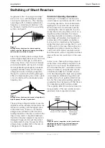
magnitudes of this “chopping overvoltage”
are .2 to 2.0 p.u. with the highest values
occurring for small reactors. The chopping
overvoltage, with its limited amplitude and
frequency, is normally quite harmless both
for the reactor itself and for the surrounding
system, see Figure 2.
Due to the oscillating reactor voltage, there
will be a high voltage stress across the circuit
breaker. If the contact gap is still small, i.e.
if the arcing time is short, the circuit breaker
probably will reignite, see Figure 3. A reigni-
tion will generate high-frequency transients
(typically hundreds of kHz) in both reactor
voltage and current. Following a reignition,
the reactor current will be interrupted again,
either at a high-frequency zero of the current,
or most probably at the subsequent power
frequency zero.
The very steep voltage transients caused by
reignitions will be unevenly distributed across
the reactor winding, with the highest stress
on the initial turns. There is a risk that the
voltage stress will lead to puncture of the
winding insulation in the reactor, which in the
long run may lead to complete breakdown.
Insulation of nearby equipment may also be
damaged. Surge arresters will only protect
to a limited extent, since the severity of the
voltage stress is related both to the rate-of-
change and to the amplitude.
Figure 2.
Voltage across shunt reactor at de-energizing
without reignition. Moderate chopping overvoltage
and moderate oscillation frequency.
Figure 3.
Voltage across shunt reactor in event of reignition. A
high-frequency transient is generated.
Control of Opening Operations
Switchsync™ controllers for shunt reactor
circuit breakers are normally used for control
of opening operations. Uncontrolled de-en-
ergizing will, in a typical case, cause reigni-
tion in at least one circuit breaker pole. By
controlling the contact separation in such a
manner that short arcing times will not occur,
reignitions will be eliminated. The remain-
ing voltage transient is a harmless chopping
overvoltage with relatively low frequency. A
normal value of the targeted arcing time is
5-6 ms, but for small reactors the targeted
arcing time may even be longer than ½ cycle
of the current. In this case, there will be no or
insignificant re-ignition transients at the first
current zero after contact separation, while
final interruption, without re-ignitions, will take
place at the second current zero of the same
phase.
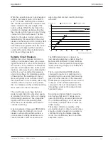
In most cases, there will be a large range of
arcing times not resulting in re-ignitions, see
Figure 4. For such cases, the adaptive func-
tion of the Switchsync™ controllers is unnec-
essary. However, by using the latest version
of Switchsync F236 for controlled shunt re-
actor de-energizing with single-pole operated
circuit-breakers unintended re-ignitions will
be detected by the re-ignition detection func-
tion. For the consecutive opening operation
an adjustment will be made such that the risk
for a repeated re-ignition will be avoided.
The re-ignition detection function is based on
measurements of the load currents and pro-
grammed contact separation instants.
Figure 4.
Target for contact separation in order to eliminate
reignitions. End of next to last current loop may
sometimes be used as target area for contact
separation.
Current
Contact separation in this time
range does not lead to reignitions
Contact separation
in this time range
leads to high risk
for reignitions
Target for
contact
separation


