


Mounting and installation
42/14-36 EN
Thermal Mass Flowmeter FMT400-VTS, FMT400-VTCS (Sensyflow VT-S/VT-CS)
23
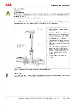
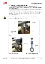
1. Pipe component with lock nut (flange version)
2. Guide tube with slip ring and guide pin. The specially processed surface of the guide tube maintains the seal
during installation and disassembly.
NOTICE
The surface of the guide tube must not be damaged. When disassembling the guide tube, the warranty
is no longer valid for ABB.
3. Covers
4. Sensyflow VT/iG transducer
Fig. 4-12
Hot tap fitting in wafer configuration for DIN flange PN 40
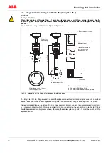
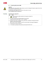
DANGER
Before disassembling the guide tube, make sure that the pipeline has been relieved of atmospheric
pressure and cleaned.
Disassembling transducers (see chapter 4.7.5)
– To disassemble the guide tube, release the 4 hex-head screws on the lock nut (Fig. 4-8) and remove the guide
tube. Clean parts, if necessary.
– Replace the two internal Viton 36 x 3 mm O-rings of the fitting and the Viton 26 x 3 mm O-ring of the guide
tube (see Fig. 4-12). Lightly lubricate the O-rings as well as the threads of the lock nut and slip ring of the guide
tube. For oxygen applications, only approved O2 fittings grease may be used (e.g., Krytox GPL-226).
– Insert the guide tube in the fitting and tighten the 4 hex-head screws of the lock nut until reaching the stop in
identical position as with disassembly.
– Verify correct installation by rotating the lock nut into measuring and disassembly positions.
!
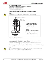
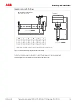
28
65
Sensyflow VT/iG transducer
Centering pin
(for flow direction)
O ring Ø 36 x 3, Viton
O ring Ø 26 x 3, Viton
Flow direction
(Transducer in measuring position)
!