


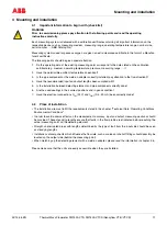


Mounting and installation
42/14-36 EN
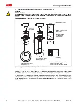
Thermal Mass Flowmeter FMT400-VTS, FMT400-VTCS (Sensyflow VT-S/VT-CS)
15
4.5
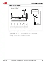
Dimensional drawings, version for process engineering
(dimensions in mm)
Transducer
Pipe component1
Wafer flange
Pipe component 2
Measuring section
Weld-on adapter
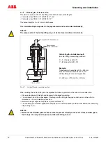
L1
B3
h
L2
B2
B1
B4
Centre of
sensor
B3
d2
d1
D1
65
h
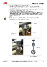
Z-18931
B3
L4
L3
h
d1
D4
(DN 25, PN 40)
L5
B3
Z-18933
Pipe
33,7
∅
PN 40
Nom. size
L2
h
D1
d1
d2
D4
L3
L4
L5
DN 25
L1 = 198
B1 = 125
B2 = 80
B3 = Ø115
B4 = 58
269
263
–
28.5
–
115
600
486
–
DN 40
94
43.1
88
150
860
731
–
DN 50
109
54.5
102
165
1000
837
–
DN 80
144
82.5
138
–
–
–
–
DN 100
170
107.1
162
–
–
–
–
DN 150
226
159.3
218
–
–
–
450
DN 200
293
206.5
285
–
–
–
> 350
431
425
>700
781
775
ANSI 150 lb, Sch 40 S
1“
L1 = 198
B1 = 125
B2 = 80
B3 = Ø115
B4 = 58
269
263
–
26.6
–
108
560
454
–
1½“
85
40.9
73
127
864
741
–
2“
103
52.6
92
154
1003
846
–
3“
135
78.0
127
–
–
–
–
4“
173
102.4
157
–
–
–
–
6“
221
154.2
216
–
–
–
450
8“
278
202.7
270
–
–
–
> 14“
431
425
> 28“
781
775
ANSI 300 lb, Sch 40 S
1“
L1 = 198
B1 = 125
B2 = 80
B3 = Ø115
B4 = 58
269
263
–
26.6
–
123.9
560
454
–
1½“
94
40.9
73
155.4
864
741
–
2“
110
52.6
92
165.1
1003
846
–
3“
148
78.0
127
–
–
–
–
4“
180
102.4
157
–
–
–
–
6“
249
154.2
216
–
–
–
450
8“
307
202.7
270
–
–
–
> 14“
431
425
> 28“
781
775