


Mounting and installation
16
Thermal Mass Flowmeter FMT400-VTS, FMT400-VTCS (Sensyflow VT-S/VT-CS)
42/14-36 EN
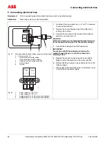
4.6
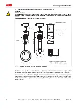
Weld-on adapter
4.6.1
Weld-on adapter for FMT400-VTS (Sensyflow VT-S) transducer
When installing the transducer in pipes with larger nominal width or non-round cross-section, the weld-on adapt-
er must be welded to the pipeline under consideration of the following information:
1.
The weld-on adapter must have a length L after welding (see Fig. 4-2 and Fig. 4-3)
L = h - ½
× ∅
D
outside
with h = 263, 425 or 775 mm (transducer lengths)
– The weld-on adapter must be shortened to the corresponding length before welding. After welding in
place, a few mm of the weld-on adapter can protrude into the pipe (max. 10 mm).
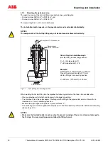
– Observe the pipeline wall thickness and amount of shrinkage when welding!
– The distance h from the flange top edge of the adapter to the pipe center line must be within a tolerance
of ± 2 mm.
2.
Rectangularity to the pipe axis must be absolutely kept (max. tolerance: 2°).
3.
The centering pin of the adapter must be aligned in flow direction to the pipe axis (at outlet run length, behind
measuring point).
4.
After welding the free passage for inserting the transducer must be at least 28 mm (if required, use drill to
clear).
5.
Transducer installation:
– Insert the supplied O-ring (55 mm
×
3 mm) into the provided groove.
– Push the transducer into the adapter and screw together.
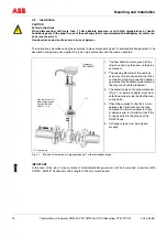
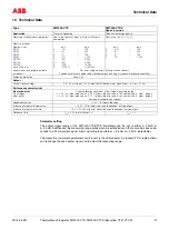
Weld-on adapter for FMT400-VTS (Sensyflow VT-S)
Fig. 4-2
Installation of the weld-adapter
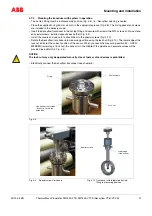
IMPORTANT
Deviations from the stated dimension and position tolerances cause additional measuring uncertainty.
Weld-on adapter
(upon delivery
Required accuracy of mounting
Centric mounting < ± 2 mm
Twist < ± 2°
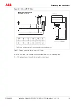
* This maximum pipe diameter
specification is only valid when
installing the sensor centrically in
the pipe. For larger diameters or
angular ducts a non-centric
sensor position is taken into
account for calibration.
Length h
of the
transducer
(in mm)
Min./max.
outer pipe
diameter
(in mm)
263
100...350
425
> 350...700
775
> 700...1400
*
∅
d
∅
D
min. 28 mm
h
Z-189341
(1)
L
Direction of flow
Sealing ring groove
(1) Centering pin
on outlet side
∅
33,7
450 mm
Z-189342
(1)
Connection flange DN 25