


Mounting and installation
42/14-36 EN
Thermal Mass Flowmeter FMT400-VTS, FMT400-VTCS (Sensyflow VT-S/VT-CS)
19
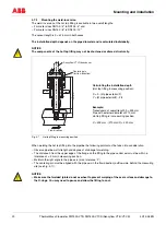
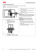
4.7.1
Technical data for integrated hot tap fittings
The hot tap fitting is designed for compressive loads of max. 16 bar. To ensure interchangeability with standard
pipe components (Design 1), the wafer flange version (Fig. 4-6) was developed for DIN flanges with a pressure
stage of PN 40. It is available in DN 50 and DN 80 formats for use with sensors with a length of 263 mm. For the
meter sizes DN 100, DN 150 and DN 200, use sensors with a length of 425 mm.
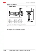
Fig. 4-5
Maximum pressure/temperature values for the integrated hot tap fitting
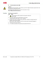
4.7.2
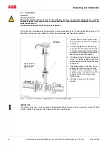
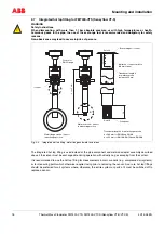
Mounting the wafer flange version
Fig. 4-6 (left) shows the wafer flange version of the hot tap fitting mounted in the pipeline in disassembly position,
i.e., the guide tube is in its upper end position and seals the Sensyflow opening (right).
The hot tap fitting is sealed on both sides with the flat gaskets against the mounting flange of the pipeline. For
greatest measurement accuracy, it must be centered exactly between the flanges, as it is for conventional pipe
components (see Fig. 4-1). Please observe the proper flow direction (arrow on pipe component).
Fig. 4-6
Hot tap fitting in disassembly position
Permissible pressure load
p_max. of the integrated hot tap fitting
0
2
4
6
8
10
12
14
16
18
0
50
100
150
200
250
T [°C]
p
[b
ar
]
Sensyflow-
opening
Temperature:
max. 200 °C
Pressure (abs.):
16 bar - 90 °C
1 bar - 200 °C