


Mounting and installation
42/14-36 EN
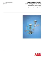
Thermal Mass Flowmeter FMT400-VTS, FMT400-VTCS (Sensyflow VT-S/VT-CS)
11
4 Mounting and installation
4.1
Important information to begin with (check list)
WARNING
Prior to commissioning please pay attention to the following points and read the operating
instructions carefully.
Each measuring system is delivered with a calibration certificate containing all important information on the
respective device such as measuring medium, measuring range, operating temperature range, nominal size,
serial number, ..., ABB Catalog No).
Measuring systems used for gaseous oxygen are given an extra clearance certificate in the form of a Manufac-
turer's certificate.
The following points should be given special attention:
1.
Do the operating data of the existing measuring point correspond to the data stated on the calibration
certificate (e.g. medium, operating temperature, pressure, measuring range, ...)?
2.
Have the permissible ambient temperatures been kept?
3.
Is the pipe component or the weld-on adapter correctly installed (pay attention to the flow direction!)?
4.
Have the recommended input and output lengths been complied with?
5.
Is the installation between detecting element and pipe component correctly done?
6.
Are the used sealings in their correct positions and in good condition?
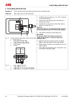
7.
Have the electrical connections U
IN
(24 V) and I
OUT
(0/4...20 mA) been correctly made?
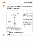
4.2
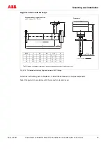
Place of installation
• The installation site must fulfill the requirements stated in the chapter "Technical Data: Operating Conditions,
Environmental Conditions".
• In order to avoid adverse effects on the measurement accuracy, input and output measuring sections should
be provided. These steadying lengths ensure that faults in the flow profile are eliminated before reaching the
actual measuring point on the detecting element.
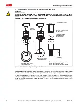
• Straight, uninterrupted pipes with lengths determined by the type of fault from the input side should be used
as steadying lengths.
• Installations of components which influence the flow rate, such as valves or shut-off fittings should possibly be
located on the output side (behind the measuring point).
• When matching up the detecting element with a weld-on adapter, please read the information in chapter 4.6.
Please make sure that the units are easily accessible when they are installed.
!