


Mounting and installation
20
Thermal Mass Flowmeter FMT400-VTS, FMT400-VTCS (Sensyflow VT-S/VT-CS)
42/14-36 EN
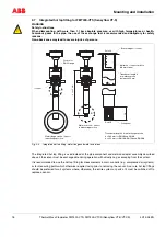
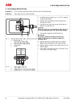
4.7.3
Mounting the weld-in version
The weld-in version of the hot tap fitting is available in two overall lengths:
– For meter sizes DN100 / 4" to DN125 / 5" and
– For meter sizes DN150 / 6" to DN300 / 12"
The sensor length is h = 425 mm in both cases.
The installation depth depends on the pipe diameter and is calculated individually.
NOTICE
The components of the hot tap fitting may not be shortened or altered structurally.
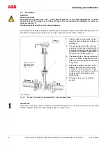
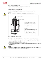
Fig. 4-7
Hot tap fitting in measuring position
When welding the hot tap fitting into the pipeline the following points must be taken into consideration:
– Observe pipeline wall strength and degree of shrinkage for welding.
– The distance h from the upper edge of the flange on the fitting to the pipe central axis must be within a
tolerance of ± 2 mm in measuring position.
– Maintain the right angle to the pipe axis (max. tolerance: 2°).
– The centering pin must be aligned with the pipe axis in the flow direction (outflow side, behind the measuring
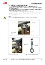
NOTICE
– Make sure that welded joints do not overheat to prevent warping of the seal surface and damage to
the O-rings. You may need to pause and allow the fitting to cool.
!
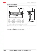
X
h
Ø50
Y
28
48
Sensyflow VT/iG transducer
Centering pin
(for flow direction)
Flow direction
(T
ransducer)
Calculating the installation depth
(Hot tap fitting in measuring position):
X = h - (Ø pipe exterior/2)
Y = (Ø pipe exterior/2) - 28
Example:
Transducers of overall length h = 425 mm
Pipe with external diameter of 210 mm
Hot tap fitting is in measuring position
X = 425 mm - (210 mm/2) = 320 mm
!