


28
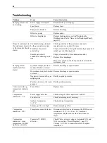
Troubleshooting
Problem Cause
Corrective
Action
Power supply interrupted
Reconnect the power supply.
Fuse blown
Replace fuses.
Pump motor blocked
Remove blockage.
Defective pump
Replace pump.
Sample gas feed unit
not working
Defective diaphragm
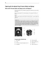
Replace diaphragm (see section"Replacing the
Diaphragm and Valve Plates in the Diaphragm Pump",
page 24).
Drops of condensate in
the condensate monitor
or flow monitor (liquid
alarm)
Condensate being produced
by the gas analysis system
Fluid from the process
penetrating
Sample gas cooler's
condensate collecting vessel
full
Check operability of the upstream condensate
separation device, and rectify cause.
Empty, clean and dry the upstream sample gas pipe and
sample gas conditioning units.
Empty, clean and dry the condensate monitor.
Replace filter diaphragm.
Press reset switch on the front panel to deactivate the
condensate lock.
Upstream sample gas line or
modules blocked or closed
Remove blockage or open modules.
Downstream modules blocked
or closed
Remove blockage or open modules.
Negative pressure on the gas
sampling side
Rectify negative pressure.
Sample gas flow
insufficient (flow
alarm)
Positive pressure in the waste
gas pipe
Rectify positive pressure.
Cooler not working,
temperature indicator
off
Fuses blown
Replace fuses.
Power supply defective
Check voltage at filter capacitors C1 and C2.
Fan defective
Check fan and replace if necessary.
Ambient temperature
> 45 °C
Check ambient temperature.
Temperature
indication > 3 °C
Sample gas flow too high
Reduce sample gas flow.
Temperature
indication = 1999
Temperature sensor defective Disconnect white leads and measure the Pt100 sensor
resistance: 107.79 + 0.4
at +20 °C ambient
temperature. Replace sensor when deviations are
larger.
Temperature
indication = room
temperature, LED K1
lights up constantly
Transistor T1 BUZ11
defective
Check Peltier element voltage at terminals X2-3 and
X2-4 (see section "Circuit Diagrams", page 35):
Voltage > 13 VDC
transistor defective; replace
transistor T1.
Summary of Contents for SCC-S
Page 1: ...SCC S Sample gas feed unit Operator s Manual 42 23 59 EN Rev 1 ...
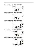
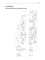
Page 35: ...35 Circuit Diagrams SCC S Sample Gas Feed Unit without Peltier Cooler ...
Page 36: ...36 SCC S Sample Gas Feed Unit with Peltier Cooler ...
Page 37: ...37 SCC S Sample Gas Feed Unit 24 VDC Power Supply and Solenoid Valves ...
Page 39: ......