


11
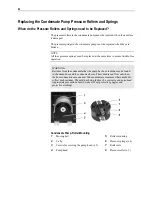
Mounting the Sample Gas Feed Unit
NOTES
Max. inclination of the instrument 5°. A distance of at least 1 height unit from
devices which develop heat is required for the version with Peltier cooler. When
mounting, allow for the additional space required for the cooling air outlet on the
left and right side of the unit (min. 3.5 cm).
Sample Gas Feed Unit Installation on the Wall
Mount the sample gas feed unit to the wall using 4 M6 screws (not supplied).
The fixing brackets required for this purpose are screwed securely on the rear of
the side panels in the factory.
To enable the cooling air to pass unobstructed into the unit to the rear, the
projection of the fixing brackets of approx. 2.5 cm to the rear wall, which is set
up in the factory, must not be reduced.
Sample Gas Feed Unit Installation in a 19-Inch Cabinet/Rack
If necessary, remove the adhesive pads from the bottom.
If necessary, install mounting rails in the cabinet/rack.
Mount the sample gas feed unit in a 19-inch cabinet/rack using 4 M6 screws (not
supplied).
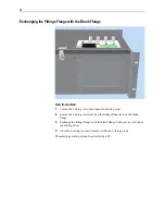
Desktop Installation
If necessary, unscrew the mounting brackets from the rear of the side panels.
If necessary, exchange the fittings flange with the blank flange.
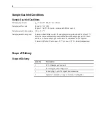
Summary of Contents for SCC-S
Page 1: ...SCC S Sample gas feed unit Operator s Manual 42 23 59 EN Rev 1 ...
Page 35: ...35 Circuit Diagrams SCC S Sample Gas Feed Unit without Peltier Cooler ...
Page 36: ...36 SCC S Sample Gas Feed Unit with Peltier Cooler ...
Page 37: ...37 SCC S Sample Gas Feed Unit 24 VDC Power Supply and Solenoid Valves ...
Page 39: ......