•
Check the mode.
•
Check the measurement value.
•
Check the connection to trip and disturbance recorder functions.
•
Check the channel settings.
8.3.2.1
Inspecting the wiring
The physical inspection of wiring connections often reveals the wrong connection for
phase currents or voltages. However, even though the phase current or voltage
connections to IED terminals might be correct, wrong polarity of one or more
measurement transformers can cause problems.
•
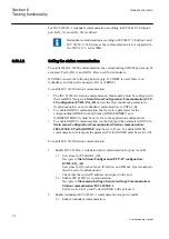
Check the current or voltage measurements and their phase information from
Main menu/Measurements/Analog primary values
or
Analog secondary
values
.
•
Check that the phase information and phase shift between phases is correct.
•
Correct the wiring if needed.
•
Change the parameter
Negation
in
Configuration/Analog modules/
3PhaseAnalogGroup/SMAI_20_n:1
(n= the number of the SMAI
used).
Changing the
Negation
parameter is not recommended
without special skills.
•
In PCM600, change the parameter
CTStarPointn
(n= the number on the
current input) under the parameter settings for each current input.
•
Check the actual state of the connected binary inputs.
•
In LHMI, select
Main menu/Tests/I/O modules
. Then navigate to the
board with the actual binary input to be checked.
•
With PCM600, right-click the product and select
Signal Monitoring
. Then
navigate to the actual I/O board and to the binary input in question. The
activated input signal is indicated with a yellow-lit diode.
•
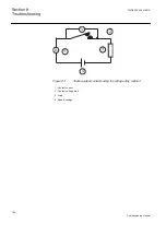
Measure output contacts using the voltage drop method of applying at least the
minimum contact load given for the output relays in the technical data, for
example 100 mA at 24 V AC/DC.
Output relays, especially power output relays, are designed for
breaking high currents. Due to this, layers of high resistance may
appear on the surface of the contacts. Do not determine proper
functionality of connectivity or contact resistance by measuring
with a regular hand-held ohm meter.
1MRK 502 049-UEN A
Section 8
Troubleshooting
123
Commissioning manual

