background image

35

USER  M A N UA L

6. Troubleshooting

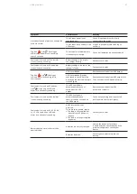
Fault event

Fault code Icon

Inverter output short

14

X

Battery voltage too high

27

X

Battery voltage too low

28

X

Over temperature

41

X

Overload

43

Charger failure

45

X

6.2.1 Faults reference code

Fault event

Fault code Icon

Bus start fail 

01

X

Bus over

02 

X

Bus under 

03 

X

Bus unbalance 

04 

X

Inverter soft start failure 

11 

X

Inverter voltage high 

12 

X

Inverter voltage low 

13 

X

6.1 Fault identification and 

rectification

Alarms and events indicate warnings and notify
of errors or potential failures in the system.
The output of the UPS is not necessarily affected
when an alarm arises but taking the correct
actions may prevent loss of power to the load

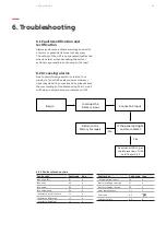
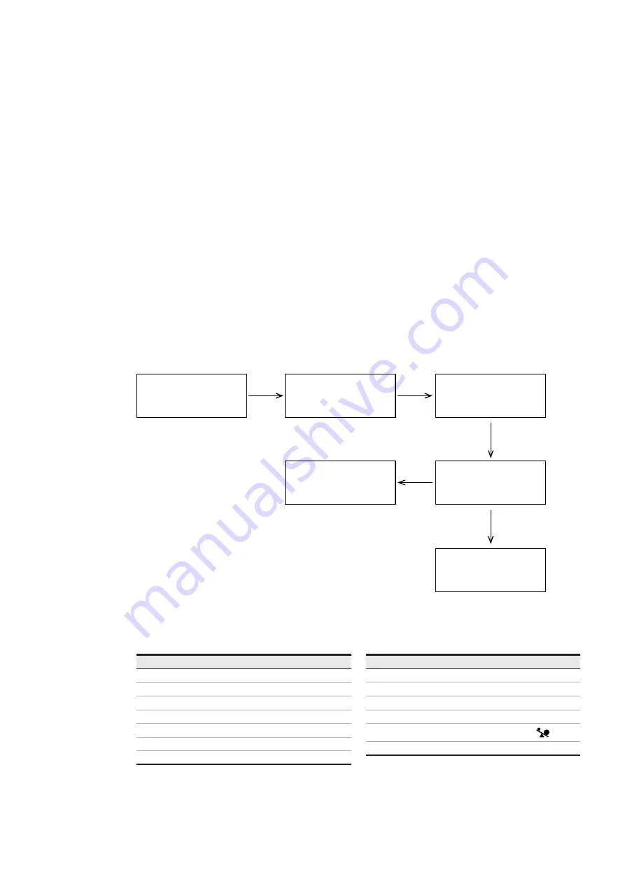
6.2 Accessing alarms

Due to careful design and strict tests of our
products, fail of UPS seldom occurs. However,
once they do fail in some situations, please check
them according to Troubleshooting Chart, which
will help you solve the most problems on UPS.

Begin

Interrupt the 
battery input

No

Yes

Return to the 

factory for repair 

If the panel LCD light 

and fan rotates?


Connect AC input

Read panel LCD to get 

the information of UPS 

on 6.2.1 and 6.2.2

Summary of Contents for PowerValue 11 RT G2 IN

Page 1: ... USER MANUAL PowerValue 11 RT G2 IN 6 10 kVA ...

Page 2: ......

Page 3: ...h the signal word WARNING indicates a potentially dangerous situation Failure to observe may cause injury death or equipment damage This symbol in conjunction with the signal word NOTE indicates operator tips or particularly useful or important information for the use of the product This symbol and wording do not indicate a dangerous situation This symbol indicates that reading the instruction man...

Page 4: ...orage 3 1 1 Receipt of the UPS and visual inspection 3 1 2 Unpacking list 3 1 3 Storage of UPS 3 2 Site planning and positioning 3 2 1 Planning before the installation 3 2 2 Positioning 3 2 3 Rack mount installation 3 2 4 Standalone tower installation 3 3 General characteristics 3 3 1 UPS front panel 3 3 2 UPS rear panel 3 4 Electrical installation 3 4 1 Commissioning 3 4 2 Recommended cable secti...

Page 5: ... shutdown 4 4 Display functions 4 5 LCD operation 4 6 LCD settings 4 7 LCD measurement functions 5 Communication 33 34 5 1 RS 232 port 5 2 USB port 5 3 Emergency power off 5 3 1 Dry IN 5 3 2 Dry OUT 5 4 Network management card optional 5 4 1 Installing a serial network management card optional 5 4 2 Monitoring software 6 Troubleshooting 35 37 6 1 Fault identification and rectification 6 2 Accessin...

Page 6: ...sure that warning label contains the following text or equivalent Isolate the UPS uninterruptible power supply before working on this circuit 1 2 Environmental considerations To operate the UPS with optimal efficiency your installation site should meet the environmental parameters outlined in this user manual Excessive amounts of dust or moisture in the operating environment may cause damage or le...

Page 7: ...should be addressed to the local ABB office or agent authorized by ABB Note the type code and the serial number of the equipment before contacting ABB or authorized agent The serial number is shown on the nameplate of the product For further information on troubleshooting see Chapter 6 1 5 Operation WARNING Do not disconnect the mains cable from the UPS or the building wiring socket during operati...

Page 8: ...nected from the mains power supply DANGER Disconnect the batteries before carrying out any kind of service and or maintenance Verify that no current is present and no hazardous voltage exists in the capacitor or bus capacitor terminals DANGER The battery circuit is not isolated from the input voltage Hazardous voltages may occur between the battery terminals and the ground Verify that no voltage i...

Page 9: ...n human health and the environment which could otherwise arise from inappropriate waste handling 2 1 UPS disposal and recycling 2 1 1 For professional users in the European Union The crossed out wheeled bin symbol on the product s and or accompanying documents means that used electrical and electronic equipment WEEE should not be mixed with general household waste If you wish to discard electrical...

Page 10: ...ved UPS corresponds to the material indicated in the delivery note Notify your carrier or supplier immediately in case of any damage 3 1 3 Storage of UPS If you plan to store the UPS prior to use keep it in a dry clean and cool storage room with an ambient temperature between 15 C to 60 C and humidity of less than 95 percent non condensing If the packing container has been removed protect the UPS ...

Page 11: ...at the h cabinet and positioning 01 02 ND SOLUTIONS the installation ce life install the unit y danger to the UPS ors e on each side of the ling airflow and ensure of air to the ventilation ed gh temperatures and urface is solid and flat an be mounted in a rack alone configuration ONDENSATION MAY OCCUR IF IS UNPACKED IN A VERY LOW ATURE TO AVOID HAZARDS AND ELECTRIC SHOCK WAIT UNTIL IS FULLY DRY B...

Page 12: ...BATTERY OSURES CAN BE CONNECTED TO UPS IN THE SAME WAY AS WN ABOVE R CONNECTING THE BATTERY OSURES CONFIGURE THE NUMBER ATTERY MODULES IN THE CONTROL L FOR MORE INFORMATION SEE TER 4 6 7 SEE APPENDIX C FOR HER DETAILS 05 3 2 4 Standalone tower installation 3 2 4 1 UPS 1 Set up the stabilizer bracket then put the unit into the stabilizer bracket figure 5 3 2 4 Standalone tower installation 3 2 4 1 ...

Page 13: ... UPS front panel Figure 8 shows the front panel of the UPS 08 UPS front panel 3 3 2 UPS rear panel The figures below show the connectors and ports in the UPS and external battery module rear panel 09 UPS rear view 10 External battery module rear view ...

Page 14: ...ect to a circuit provided with branch circuit overcurrent protection for D curve 63 A rating upstream circuit for 6kva models D curve 80 A rating upstream circuit for 10kva models Table 4 Recommended cable cross sections Model 6K 10K Protective earthing conductor min cross section 10 mm 2 8 AWG 16 mm 2 6 AWG Input L N G min conductor cross section 10 mm 2 8 AWG 16 mm 2 6 AWG Input fuse 63 A 80 A O...

Page 15: ...e expected to cause the failure of the life support equipment or to significantly affect its safety or effectiveness is not recommended Do not use this equipment in the presence of a flammable anesthetic mixture with air oxygen or nitrous oxide WARNING Do not connect appliances or devices which would overload the OVCD box WARNING Do not install the OVCD near water or in moist environments WARNING ...

Page 16: ...put power From Utility I P Breaker I P Breaker I P Breaker I P Breaker Mains Breaker Maintain Bypass for Parallel O P Breaker O P Breaker O P Breaker O P Breaker Main O P Breaker To Load Mains Mechanical or static switch UPS 1 UPS 2 UPS 3 UPS 4 16 Parallel system installation diagram Connect UPS and OVDC box as shown in Figure 15 15 PDU terminal block access ...

Page 17: ...rs and a main maintenance mechanical switch or static switch 2 Independent battery packs for each UPS 3 Remove the cover plate from the parallel connection port on the UPS connect each UPS one by one with a parallel connection cable and make sure the cable is screwed in tightly 17 Parallel cable connection 17 Parallel system wiring diagram ...

Page 18: ...switch off the main output breaker input breaker and mains breaker The UPS will then shut down 5 Connect the cable and wire for the new UPS 6 Switch on the input breakers and mains breaker and make sure that every UPS is in bypass mode 7 Switch on the output breakers and main output breaker transfer the main maintenance switch or static switch from BPS to UPS 8 Press the button on one UPS all the ...

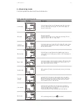
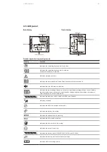
Page 19: ...PS will be in standby mode under power normal or will transfer to bypass mode if the bypass enable is set when this button is pressed Confirm selection key Press this button to confirm selection in UPS settings mode SELECT Select button Switch LCD message Press this button to change the LCD message for input voltage input frequency battery voltage output voltage and output frequency It will revert...

Page 20: ...ry Buzzer beeps every second Bypass Beep every 10 minutes Overload Beep twice every second When powering on the LCD shows the UPS status The UPS will also return to this default screen when no buttons have been pressed for 15 minutes The status screen shows the following information Status summary including operating mode and load information Alarm status if present including fault and warning inf...

Page 21: ...e or power failure and alarm are sounding every 4 second UPS will backup power from battery Bypass mode When input voltage is within acceptable range but UPS is overloaded UPS will enter bypass mode or bypass mode can be set from front panel Alarm sounds every 10 seconds Standby mode UPS is powered off and no output supply power but still can charge batteries Overload warning When the UPS is in ov...

Page 22: ...ns supply 1 If the UPS is working in bypass mode go to step 3 2 If the UPS is in online mode keep the power button pressed for more than 3 seconds The alarm buzzer will sound and the UPS will transfer to bypass mode DANGER The output is still energized 3 Disconnect the mains power supply The display will shut down and the output voltage will be removed from the UPS output terminal 4 If the bypass ...

Page 23: ...attery voltage output current battery capacity load percent output power positive bus voltage negative bus voltage temperature output receptacle 1 output receptacle 2 Indicates the load level 0 25 26 50 51 75 and 76 100 Indicates overload Indicates the UPS is connected to the mains Indicates the battery is working Indicates the bypass circuit is working Indicates the ECO mode is enabled Indicates ...

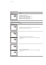
Page 24: ...tage setting Interface Settings Parameter 1 Output voltage Set up output voltage You may choose the following output voltage 208 output voltage is 208 Vac 220 output voltage is 220 Vac 230 output voltage is 230 Vac default 240 output voltage is 240 Vac 02 Frequency converter enable disable Interface Settings Parameter 1 Enable or disable converter mode You may choose from the following two options...

Page 25: ... 240 presents output voltage is 240Vac 05 ECO voltage range settings Interface Settings Parameter 1 Set the acceptable high voltage point and low voltage point for ECO mode by pressing Down key or Up key HLS High loss voltage in ECO mode in parameter 1 The setting range in parameter 2 is from 5 to 10 of the nominal voltage Default 5 LLS Low loss voltage in ECO mode The setting range in parameter 2...

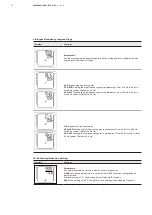
Page 26: ...in ECO mode in parameter 1 The setting range in parameter 2 is from 5 to 10 of the nominal voltage Default 5 LLS Low loss frequency in ECO mode in parameter 1 The setting range in parameter 2 is from 5 to 10 of the nominal voltage Default 5 07 Bypass enable disable when UPS is off Interface Settings Parameter 1 Enable or disable Bypass function You may choose the following two options ENA Bypass e...

Page 27: ...nt and low voltage point for Bypass mode by pressing the Down key or Up key HLS Bypass high voltage point 245 276 Sets the high voltage point in parameter 2 from 245 Vac to 276 Vac Default 264 Vac LLS Bypass low voltage point 120 215 Sets the low voltage point in parameter 2 from 120 Vac to 215 Vac Default 184 Vac ...

Page 28: ...0 Hz for 60 Hz system Default 64 0 Hz LLS Bypass low frequency point 46 0 49 0 Setting the low frequency point in parameter 2 from 46 0 Hz to 49 0 Hz for 50 Hz system Default 46 0 Hz 56 0 59 0 Setting the low frequency point in parameter 2 from 56 0 Hz to 59 0 Hz for 60 Hz system Default 56 0 Hz 10 Autonomy limitation setting Interface Settings Parameter 1 Set up backup time on battery mode for ou...

Page 29: ...ontact Interface Settings Parameter 1 Set input dry contact DIS Disable the function Default TON UPS Turn On TOF UPS Turn Off MBS Maintain Bypass 14 Output dry contact Interface Settings Parameter 1 Set output dry contact SAL Summary alarm Default BTA Battery active LBA Low battery UPN UPS normal BSA Bypass active 15 EPO Interface Settings Parameter 1 Clear EPO warning EPO active the UPS output is...

Page 30: ...tart enable disable Interface Settings Parameter 1 Set DC start ENA DC start enable Default DIS DC start disable 19 Ambient temperature warning Interface Settings Parameter 1 Set ambient temperature warning ENA Ambient temperature warning enable Default DIS Ambient temperature warning disable 20 Automatic battery test Interface Settings Parameter 1 Set automatic battery test 0 31 days Default 7 da...

Page 31: ...ble Default 24 Outlet 1 Interface Settings Parameter 1 Set Outlet 1 ON Outlet 1 On Default OFF Outlet 1 Off 25 Charging current setting Interface Settings Parameter 1 Set charging current for S model You may choose the following charging current 1 12A Step 1A 1 0 presents charging current is 1 0A 2 0 presents charging current is 2 0A 4 0 presents charging current is 4 0A Default 6 0 presents charg...

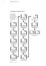
Page 32: ...A T T B A T T L L O A D 2 5 5 0 7 5 1 0 0 L O A D VAC 2 5 5 0 7 5 1 0 0 B A T T B A T T L L O A D 2 5 5 0 7 5 1 0 0 L O A D 2 5 5 0 7 5 1 0 0 B A T T B A T T L L O A D 2 5 5 0 7 5 1 0 0 L O A D 2 5 5 0 7 5 1 0 0 B A T T B A T T L L O A D 2 5 5 0 7 5 1 0 0 L O A D 2 5 5 0 7 5 1 0 0 B A T T B A T T L L O A D 2 5 5 0 7 5 1 0 0 L O A D 2 5 5 0 7 5 1 0 0 B A T T B A T T L L O A D 2 5 5 0 7 5 1 0 0 L O ...

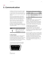
Page 33: ...UPS and the other end to the RS 232 port of a computer The cable pins for the RS 232 communication port are described in Figure 5 1 1 and Table 7 5 1 1 RS 232 Communication Port DB 9 Connector Table 7 Communication port pin assignment PIN Signal name Function Direction from UPS 2 TxD Transmit to external device Out 3 RxD Receive from external device in 5 GND Signal common 5 2 USB port The UPS can ...

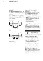
Page 34: ...S400 communication protocol 5 4 1 Installing a serial network management card optional Each UPS has a communication slot for an optional serial network management protocol SNMP Modbus card After installing an SNMP Modbus card an environmental monitoring probe can be connected NOTE The UPS does not have to be shuts down before installing a Communication card To install a network management card 1 R...

Page 35: ... events indicate warnings and notify of errors or potential failures in the system The output of the UPS is not necessarily affected when an alarm arises but taking the correct actions may prevent loss of power to the load 6 2 Accessing alarms Due to careful design and strict tests of our products fail of UPS seldom occurs However once they do fail in some situations please check them according to...

Page 36: ...ice every second Battery is not connected Sounding every second Over charge Sounding every second Over temperature Sounding every second Charger failure Sounding every second Battery fault Sounding every second Out of bypass voltage range Sounding every second Bypass frequency unstable Sounding every second EEPROM error Sounding every second ...

Page 37: ...directly by the electrical network via the bypass Remove excess loads from UPS output first Then shut down the UPS and restart it Fault code is shown as 43 and the icon is lighting on LCD and alarm is continuously sounding The UPS shuts down automatically because of overload at the UPS output Remove excess loads from UPS output and restart it Fault code is shown as 14 and alarm is continuously sou...

Page 38: ...ight 2022 ABB All rights reserved Specifications subject to change without notice ABB India Helpline Technical telephone support for customers and channel partners Toll free BSNL 91 1800 420 07 07 abb com ups ...

Reviews: