


Navigator ADS551 | Low level dissolved oxygen | Replacement / Upgrade procedures – wet section spares |
INS/ANAINST/025-EN Rev. B
7
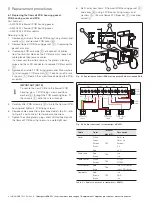
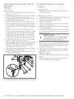
6.6 Replacing the Modbus cable assembly
Part numbers:
— AW502 090 / 1.5 m (4.9 ft.)
— AW502 091 / 5 m (16.4 ft.)
— AW502 092 / 10 m (32.8 ft.)
— AW502 093 / 20 m (65.6 ft.)
Referring to Fig. 6.1, page 4:
1.
Remove the PCB cover.
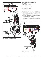
Referring to Fig. 6.7:
2.
Loosen cable gland
A
at the wet-section PCB housing
B
and disconnect the Modbus cable
C
from terminal
block connections
D
(TB1) marked white, green, screen,
black and red.
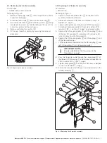
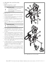
3.
Withdraw Modbus cable
C
from the PCB housing and
flowcell case assembly and discard.
4.
Feed the replacement Modbus cable through cable gland
A
and remake connections to the (TB1) white, green,
screen, red and black terminal connections at the wet
section PCB and at the transmitter.
5.
Refit the PCB cover by reversing the removal procedure.
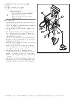
Fig. 6.6 Replacing the temperature sensor assembly
E
TB1
TB3
TB5
TB4
TB2
White
Green
Screen
Red
Black
Red
Black
White
Screen
Red
Blue Red Brown Black
F
Fig. 6.7 Replacing the Modbus cable assembly
TB1
TB3
TB5
TB4
TB2
White
Green
Screen
Red
Black
Red
Black
White
Screen
Red
Blue Red Brown Black


