6
INS/ANAINST/025-EN Rev. B
| Navigator ADS551 | Low level dissolved oxygen | Replacement / Upgrade procedures – wet section spares
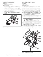
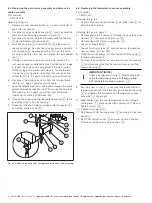
6.4 Replacing the drain valve assembly and drain valve
cable assembly
Part number:
— AW502 056
Referring to Fig. 6.5:
1.
Depress manual override button
A
on drain valve
B
to
drain the wet-section.
2.
Disconnect clip-on cable connector
C
from the end of the
drain valve coil housing by depressing clip
D
.
3.
Disconnect the drain tube from barbed outlet connector
E
on the bottom of drain valve
B
.
4.
Lock hex coupling
G
and rotate nut
H
clockwise to
release couplings. Remove the valve assembly, complete
with coupling
G
. Remove coupling
G
from the valve
assembly and fit to new valve, complete with new bonded
seal
I
.
5.
If fitting a new drain valve cable assembly, remove the
wet-section cover as detailed in step 1 of Section 6.1, page
4, loosen the drain valve cable gland in the wet-section
PCB housing and proceed with steps 6, 7and 8 (below).
If using the existing cable, re-connect the clip-on cable
connector
C
to the end of the drain valve coil housing.
6.
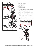
Disconnect the drain valve cable from the terminal block –
see Fig. 6.7, page 7 and discard the cable.
7.
Feed the replacement drain valve cable through the cable
gland and make connections to PCB wet-section terminals
TB3 (see Fig. 6.3, page 5) and at the transmitter (see
Operating instruction OI/ADS550-EN).
8.
Connect the drain valve clip-on cable connector
C
to the
end of the drain valve coil housing.
9.
Reconnect the drain tube to barbed outlet connector
E
on bottom of drain valve
B
.
6.5 Replacing the temperature sensor assembly
Part number:
— AW502 220
Referring to Fig. 6.5:
1.
Depress manual override button
A
on drain valve
B
to
drain the wet-section.
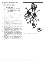
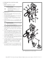
Referring to Fig. 6.6, page 7:
2.
Remove and retain 4 flowcell PCB cover fixing screws and
washers
C
and remove PCB cover
D
.
3.
Remove flowcell PCB housing gasket
E
.
4.
Loosen cable gland
F
.
5.
Loosen terminal screws
G
and disconnect temperature
sensor cables
H
from TB5.
6.
Withdraw sensor cables
H
from flowcell PCB housing
I
through cable gland
F
.
7.
Unscrew the knurled nut on temperature sensor assembly
J
and carefully withdraw the temperature sensor from
flowcell housing
K
.
8.
Ensure a new O-ring
L
is securely located on the new
temperature sensor, insert the sensor into flowcell housing
K
and tighten the knurled nut on temperature sensor
assembly
J
finger-tight.
9.
Feed cables from the new temperature sensor through
cable gland
F
, make connections correctly at TB5 and
tighten screws
G
.
10. Tighten cable gland
F
.
11. Refit flowcell PCB housing gasket
E
ensuring it is located
correctly.
12. Refit PCB flowcell cover
D
and secure with 4 flowcell
PCB cover fixing screws and washers
C
.
Fig. 6.5 Replacing the drain valve assembly and drain valve cable assembly
A
B
C
D
E
F
G
H
I
IMPORTANT (NOTE)
Check existing small O-ring
L
fitted on the end
of the temperature sensor is withdrawn along
with temperature sensor assembly
J
.

