


Navigator ADS551 | Low level dissolved oxygen | Replacement / Upgrade procedures – wet section spares |
INS/ANAINST/025-EN Rev. B
9
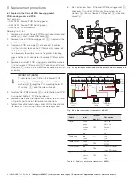
7 Upgrade procedures
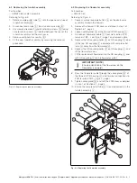
7.1 Upgrading the flowmeter
Part number:
— AW502 250
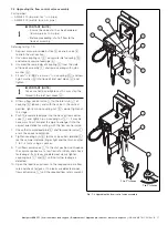
Referring to Fig. 7.1:
1.
Depress manual override button
A
on the drain valve
assembly to drain the flowcell.
2.
Remove outlet tube
B
from QD coupling
C
by
depressing collar
D
on QD coupling
C
and pulling tube
B
up.
3.
Unscrew and remove QD coupling
C
and wipe up any
water spillage.
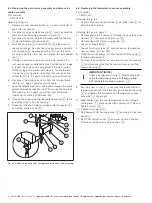
4.
Screw new QD coupling
C
in and fit:
— flowmeter
E
— (upper) QD coupling
F
— sample outlet tube
G
5.
Remove the flowcell PCB cover as detailed in step 1 of
Section 6.1, page 4.
6.
Remove blanking plug
I
from front of flowcell PCB
housing
J
and replace with supplied cable gland (and
O-ring)
K
.
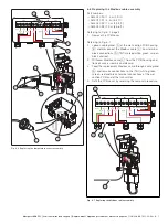
7.
Pass flowmeter cable
L
through cable gland
K
at
flowcell PCB housing
J
and make connections to PCB
terminal block TB2 – refer to Fig. 6.7, page 7.
8.
Tighten cable gland
K
to form a watertight seal.
9.
Check sample outlet tube
G
is located correctly over
tundish assembly
H
and restart sample flow.
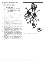
Referring to Operating instruction OI/ADS550-EN:
10. Configure the transmitter to read the output from the
flowmeter by selecting
Sensor Setup
, scrolling to
Flowmeter
and selecting
Enabled
.
(This enables auto calibrations to be configured.)
IMPORTANT (NOTE)
Ensure sample outlet tube
G
is located
correctly over tundish assembly
H
.
Fig. 7.1 Upgrading the flowmeter assembly
Upgraded flowmeter fitted and connected