background image

Reference   49

Object dictionaries

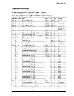
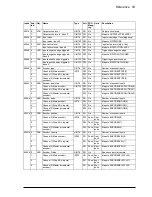
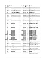
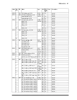
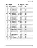
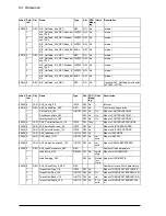
EtherCAT protocol objects: 1000h - 2000h

The following objects are specific to EtherCAT communications:

Index Sub-

ind.

Object

Name

Type

Attr.

PDO
mapping

Content 
example

1000h 0

VAR

NMT_DeviceType_U32

UINT32

CONST No

131474

1001h 0

VAR

ERR_ErrorRegister_U8

UINT8

RO

Poss.

0

1008h 0

VAR

NMT_ManufactDevName_VS

STRING CONST No

MotiFlex e180

1009h 0

VAR

NMT_ManufactHwVers_VS

STRING CONST No

100Ah 0

VAR

NMT_ManufactSwVers_VS

STRING CONST No

MotiFlex e180 
Build 581.3.0 
(mCard)

1010h 0

REC

NMT_StoreParam_REC

UINT8

RO

No

1

1

NMT_StoreParam_REC.AllParam_U32

UINT32

RW

No

1

1011h 0

REC

NMT_RestoreDefParam_REC

UINT8

RO

No

1

1

NMT_RestoreDefParam_REC.AllParam_U32

UINT32

RW

No

1

1018h 0

REC

NMT_IdentityObject_REC

UINT8

RO

No

4

1

VendorId_U32

UINT32

CONST No

183

2

ProductCode_U32

CONST No

700

3

RevisionNo_U32

CONST No

374603778

4

SerialNo_U32

CONST No

1112130069

10F3h 0

REC

DGN_DiagnosisHistory_REC

UINT8

RO

No

21

1

MaximumMessages_U8

UINT8

RO

No

16

2

NewestMessage_U8

UINT8

RO

No

21

3

NewestAcknowledgedMessage_U8

UINT8

RW

No

21

4

NewMessagesAvailable_BOOL

BOOL

RO

Poss.

False

5

Flags_U16

UINT16

RW

No

0

6

DiagnosisMessage_0_OSTR

OCTET_
STRING

RO

No

00000...

7

DiagnosisMessage_1_OSTR

RO

No

00000...

8

DiagnosisMessage_2_OSTR

RO

No

00000...

9

DiagnosisMessage_3_OSTR

RO

No

00000...

10

DiagnosisMessage_4_OSTR

RO

No

00000...

11

DiagnosisMessage_5_OSTR

RO

No

00000...

12

DiagnosisMessage_6_OSTR

RO

No

00000...

13

DiagnosisMessage_7_OSTR

RO

No

00000...

14

DiagnosisMessage_8_OSTR

RO

No

00000...

15

DiagnosisMessage_9_OSTR

RO

No

00000...

16

DiagnosisMessage_10_OSTR

RO

No

00000...

17

DiagnosisMessage_11_OSTR

RO

No

00000...

18

DiagnosisMessage_12_OSTR

RO

No

00000...

19

DiagnosisMessage_13_OSTR

RO

No

00000...

20

DiagnosisMessage_14_OSTR

RO

No

00000...

21

DiagnosisMessage_15_OSTR

RO

No

00000...

1600h 0

ARRAY

PDO_ReceiveMapping_0_AU32

UINT8

RW

No

2

1

PDO_ReceiveMapping_0_AU32[1]

UINT32

RW

No

1614807056

...

...

...

...

...

254

PDO_ReceiveMapping_0_AU32[254]

RW

No

0

Summary of Contents for MotiFlex e180

Page 1: ...ABB motion control Application guide MotiFlex e180 EtherCAT ...

Page 2: ... the Document library contact your local ABB representative Drive hardware manuals and guides Code English MotiFlex e180 Quick Installation Guide 3AXD50000017336 MotiFlex e180 User s Manual 3AXD50000019946 MotiFlex e180 Wall chart 3AXD50000019945 MotiFlex e180 Common DC Application Guide 3AXD50000019947 MotiFlex e180 CE Declaration of Conformity 3AXD10000371048 MotiFlex e180 STO Certificate 3AXD10...

Page 3: ...e MotiFlex e180 EtherCAT 3AXD50000048672 Rev B EN EFFECTIVE 2017 01 30 2017 ABB UK All Rights Reserved 1 Safety Table of contents 4 Mechanical installation 6 Electrical installation AC input motor and brake 4 Start up ...

Page 4: ......

Page 5: ... Related documents 16 Trademarks 16 3 Physical connection What this chapter contains 17 Product overview 17 EtherCAT ports 18 E1 E2 Ethernet port configuration 19 4 Start up What this chapter contains 21 Safety 21 Introduction 21 Connect the MotiFlex e180 to the PC 21 Configure the PC Ethernet adapter 22 Install Mint WorkBench 22 Enable the Ethernet adapter for Mint WorkBench 23 Start the MotiFlex...

Page 6: ...sh periods 36 Drive status display 37 Power 39 Communication 39 Mint WorkBench 39 Ethernet 40 6 Reference What this chapter contains 41 Introduction 42 Supported mailbox protocols 42 Synchronisation 42 Setting the control reference source 43 Resetting position 43 NMT state machine 44 Object dictionary 46 Error codes and detection 46 Object 4144h First Error 48 Emergency Messages 48 Diagnosis Objec...

Page 7: ... injury or death and or damage to the equipment and advise on how to avoid the danger The following warning symbols are used in this manual Electricity warning warns of hazards from electricity which can cause physical injury and or damage to the equipment General warning warns about conditions other than those caused by electricity which can result in physical injury and or damage to the equipmen...

Page 8: ...circuits Externally supplied control circuits may cause dangerous voltages inside the drive even when the main power on the drive is switched off Do not make any insulation or voltage withstand tests on the drive Do not connect the drive to a voltage higher than what is marked on the type designation label Higher voltage can activate the brake chopper and lead to brake resistor overload or activat...

Page 9: ...ake sure that grounding conductors are adequately sized as required by safety regulations In a multiple drive installation connect each drive separately to protective earth PE Where EMC emissions must be minimized make a 360 high frequency grounding of cable entries in order to suppress electromagnetic disturbances In addition connect the cable shields to protective earth PE in order to meet safet...

Page 10: ...according to step 1 or 2 or if possible according to the both steps 1 Disconnect the motor from the drive with a safety switch or by other means Check by measuring that there is no voltage present on the drive input or output terminals L1 L2 L3 U1 V1 W1 UDC UDC R R 2 Ensure that the motor cannot rotate during work Make sure that no other system like hydraulic crawling drives is able to rotate the ...

Page 11: ... drive system components such as the mains choke DC choke or braking resistor if present become hot when the system is in use and remain hot for a while after disconnection of the electrical supply Ensure that debris from drilling and grinding does not enter the drive when installing Electrically conductive debris inside the unit may cause damage or malfunction Ensure sufficient cooling Do not att...

Page 12: ... drive or a fieldbus adapter The maximum allowed number of charging cycles of the DC capacitors i e power ups by applying power is one per two minutes The maximum total number of chargings is 100000 for frame sizes A and B 50000 for frame sizes C and D Make sure that any safety circuits for example emergency stop and Safe torque off are validated in start up See chapter Start up for reference of t...

Page 13: ...ure connection between the product and your network or any other network as the case may be You shall establish and maintain any appropriate measures such as but not limited to the installation of firewalls application of authentication measures encryption of data installation of anti virus programs etc to protect the product the network its system and the interface against any kind of security br...

Page 14: ...14 Safety ...

Page 15: ...de Both SI and imperial units are shown Contents of this manual The manual consists of the following chapters Safety page 7 gives safety instructions you must follow when installing commissioning operating and servicing the drive Introduction to the manual this chapter page 15 describes applicability target audience purpose and contents of this manual It also contains a quick installation and comm...

Page 16: ...ated documents See List of related manuals on page 2 inside the front cover Trademarks EtherCAT is registered trademark and patented technology licensed by Beckhoff Automation GmbH Germany TwinCAT is a registered trademark of Beckhoff Automation GmbH Windows 7 and Windows 8 are registered trademarks of the Microsoft Corporation Mint and MotiFlex are registered trademarks of Baldor a member of the ...

Page 17: ...he chapter briefly describes how to connect the MotiFlex e180 to an EtherCAT network Product overview The MotiFlex e180 is an IP20 drive module for controlling AC motors All models support EtherCAT slave operation under the control of an EtherCAT master device or application ...

Page 18: ... such as EtherCAT In an EtherCAT network the E1 IN port must be connected to the master side of the network The E2 OUT port if used must be connected to the IN port of the next slave device in the network Standard CAT5e or CAT6 Ethernet cables can be used 1 2 3 4 5 6 7 8 TX TX RX NC NC RX NC NC Pin 1 Link Activity EtherCAT master IN IN IN OUT OUT ...

Page 19: ...of operation for the Ethernet fieldbus connectors E1 and E2 on the top panel of the drive Set both front panel rotary HI LO switches to 0 to select EtherCAT slave mode See MotiFlex e180 indicators on page 35 for a description of the fieldbus status indicators Value Mode 00 EtherCAT slave mode 01 EF Ethernet POWERLINK CN mode selected value is node ID F0 Reserved F1 Reserved F2 FF Reserved HI LO ...

Page 20: ...20 Physical connection ...

Page 21: ...nt WorkBench software on the PC This includes a number of applications and utilities to allow you to configure tune and program the MotiFlex e180 Mint WorkBench and other utilities can be downloaded from the SupportMe pages of www abbmotion com Connect the MotiFlex e180 to the PC Connect a CAT5e or CAT 6 Ethernet cable between the PC and the MotiFlex e180 E3 Ethernet port on the front panel Do not...

Page 22: ...ated on the network 1 On the Windows 7 Start menu choose Control Panel then Network and Sharing Center Windows 8 1 From the Start screen click the down arrow or swipe up to go to the Apps screen Choose Control Panel Network and Internet Network and Sharing Center 2 On the left of the window click Change Adapter Settings Double click the icon for the required Ethernet adapter then click Properties ...

Page 23: ...s approximately 15 20 seconds The sequence ends with the symbol or if an STO input page 175 is not powered Startup can take more than 1 minute after downloading new firmware 4 To allow the Commissioning Wizard to function the Safe Torque Off inputs page 175 need to be powered to allow the MotiFlex e180 to be enabled Start Mint WorkBench Mint WorkBench is a fully featured application for programmin...

Page 24: ... relating to the EtherCAT connection 1 Click the EtherCAT tool icon in the Toolbox on the left of the screen 2 Wait until data is uploaded from the MotiFlex e180 3 The Summary tab shows basic information about the EtherCAT connection 4 Click Save as to create an ESI file for the MotiFlex e180 This file can be imported into your EtherCAT master 5 The Object Dictionary tab displays the current state...

Page 25: ...are not required 1 Open a web browser 2 In the address bar enter the IP address of the MotiFlex e180 e g 192 168 0 1 The drive will provide a basic information screen 3 In the Fieldbus description files area click the link to download the ESI file If the web browser cannot find the MotiFlex e180 it may be due to your network using an HTTP proxy causing all requests entered in the browser to be for...

Page 26: ...hows how to use TwinCAT to upload and download files to the MotiFlex e180 1 Check that the drive is connected to the PC via EtherCAT 2 In the TwinCAT Solution Explorer right click on the Devices node and scan for devices 3 Select the device that has EtherCAT beside its name and click OK 4 Click Yes twice to add the drive to the NC Configuration 5 Click Yes twice to add the drive to the NC Configur...

Page 27: ...Start up 27 7 Now select the drive by double clicking its node in the tree double click Drive 1 if the tabbed window is not displayed 8 Activate the Run mode ...

Page 28: ...eptable as a file name but the prefix must be omitted when entering the string name for the file The entry for String in the Edit FoE Name dialogue must be one of the following FIRMWARE FPGA CONFIG MINT See the table on page 26 for details 11 Click OK to confirm the FoE Name details The file will be uploaded using the FoE protocol onto your PC s hard drive It may take a few seconds if the file is ...

Page 29: ...to the drive access the File Access over EtherCAT options as described in steps 1 to 8 above 2 Click the Download button 3 You can open any file e g a hex firmware file using the Open dialogue box but the FoE name must be either FIRMWARE FPGA CONFIG or MINT It may take a few seconds if the file is large ...

Page 30: ...d on reset object it cannot do so while the drive is operating To change a valid on reset object value the following steps are performed The object is modified in RAM according to the user s changes The configuration is downloaded to the drive and stored The drive is reset This causes the default values to be loaded followed by the configuration file containing the changed object which overwrites ...

Page 31: ...on value write the value 0x65766173 evas save to object 1010 01 Deleting the stored configuration Write 0x64616F6C daol load to 1011 01 to delete the stored configuration and set all objects to their default values Configuration object operations Default value Default value Configuration value Non volatile stored value Current value Value of object in RAM changed locally or by master Mint Live val...

Page 32: ... use an ABB AC500 PLC to home the drive AN221 AC500 and MicroFlex e150 EtherCAT Fast Position Capture describes how to use an ABB AC500 PLC to capture the drive s axis AN234 Generic Drive Interface via EtherCAT for Simple Motion describes how to use a simple ready made drive control protocol to access the drive s NETDATA array AN242 Accessing Drive Parameters via EtherCAT SDO describes how to modi...

Page 33: ...ch use the Error Log tool to view recent errors and then check the help file If you cannot solve the problem or the problem persists the SupportMe feature can be used SupportMe feature The SupportMe feature is available from the Help menu or by clicking the button on the motion toolbar SupportMe can be used to gather information which can then be e mailed saved as a text file or copied to another ...

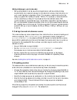
Page 34: ...or data you entered selected in the Commissioning Wizard the gain settings generated during the tuning process and any gain settings you have entered yourself Power cycling the MotiFlex e180 The term power cycle the MotiFlex e180 is used in the Troubleshooting sections Remove the 24 V supply wait for the MotiFlex e180 to power down completely the Status LED turns off then re apply the 24 V supply ...

Page 35: ...ory Invalid request state change Unknown requested state Bootstrap not supported No valid firmware No valid inputs available No valid output Synchronisation error Invalid Sync manager types Slave needs cold start Slave needs INIT Slave needs PREOP Slave needs SAFEOP Invalid input mapping Invalid output mapping Inconsistent settings FreeRun not supported SyncMode not supported FreeRun needs 3 buffe...

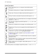
Page 36: ...reen Off INITIALISATION state or not powered Blinking PRE OPERATIONAL state 1 flash SAFE OPERATIONAL state 3 flashes Device identification This state can be set from the master to locate the device Continuously illuminated not flashing Node in OPERATIONAL state EtherCAT is operating normally 200 ms 1 s 1 s 1 s 1 s 1 s Off 1 flash 2 flashes Inverted 2 flashes 3 flashes etc Blinking Flickering On No...

Page 37: ...d and one or both STO inputs are not powered The drive must be enabled before operation can continue Both STO inputs must be powered If an optional drive enable input has been configured it must also be powered Drive disabled The drive must be enabled before operation can continue If an optional drive enable input has been configured it must also be powered Suspend active The Mint SUSPEND command ...

Page 38: ...int keywords JOG JOGCOMMAND and related topics Offset move An offset move is in progress See the Mint keyword OFFSET Position move A linear move is in progress See the Mint keywords MOVEA and MOVER Torque move The drive is in torque mode See the Mint keywords TORQUEREF TORQUEREFSOURCE and related commands Firmware recovery mode in operation see Linear switches startup functions on page 77 Stop inp...

Page 39: ...cable is connected between the PC and MotiFlex e180 Check that the cable is connected to port E3 on the front panel and not port E1 or E2 Check that the PC s Ethernet port has been correctly configured for TCP IP operation and enabled for use with Mint WorkBench see Configure the PC Ethernet adapter on page 22 Check that the correct Ethernet adapter has been selected see Enable the Ethernet adapte...

Page 40: ... take control of the MotiFlex e180 There are several ways to do this Set the CONTROLREFSOURCESTARTUP parameter to 1 using the Mint WorkBench Parameter viewer or Command window and restart the drive This gives control to the manager each time the MotiFlex e180 starts Set the Control Ref Source to RT Ethernet CiA402 in the Mint WorkBench Operating Mode Wizard or Commissioning Wizard Click the Direct...

Page 41: ...Reference 41 6 Reference What this chapter contains This chapter contains reference information about the MotiFlex e180 EtherCAT implementation ...

Page 42: ...ard Ethernet switches can be used in EtherCAT networks The MotiFlex e180 has passed the formal EtherCAT conformance test which is performed using a network with a wide range of EtherCAT devices It has also been tested with many different types of master device to ensure interoperability including ABB AC500 PLC with EtherCAT master CM579 ETHCAT acontis technologies EC master stack and EC Win Beckho...

Page 43: ...ally the master sets it due to a start up command in the installed ESI file but there are other ways to set the control reference source Use an SDO write to object 0x5002 Set the CONTROLREFSOURCE to 1 _crsRT_ETHERNET_402 using the Parameters tool or Command window in Mint WorkBench Set the Control Ref Source item to RT Ethernet CiA402 on the Select Operating Mode and Source page of the Mint WorkBe...

Page 44: ...er and application drive profile specific objects 0x2000 and greater to their power on values NMT_GS_RESET_COMMUNICATION Reset communication is used to set all communication profile specific objects 0x1000 1FFF to their power on values NMT_GS_RESET_CONFIGURATION Reset configuration is used to apply the configuration settings Objects that are handled during that state are marked with valid on reset...

Page 45: ...unication NMT GT13 EtherCAT to INIT NMT_GT4 NMT_ResetNode NMT_GS_POWERED NMT_GS_INITIALISATION NMT_GT10 auto NMT_GT1 PowerOn NMT_GT11 auto NMT_GT12 auto NMT_GS_INITIALISING NMT_GS_RESET_APPLICATION NMT_GS_RESET_COMMUNICATION NMT_GS_RESET_CONFIGURATION NMT_GS_CONFIGURATION_ERROR NMT_GS_COMMUNICATING NMT_CS NMT CN STATE MACHINE NMT_GT3 PowerOff NMT_MS NMT MN STATE_MACHINE NMT_EMS NMT EtherCAT MASTER...

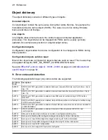
Page 46: ...lowing application layer AL status codes are supported AL Status Code Description 0x002D SYNC0 or SYNC1 generation is enabled but never received after time out Cycle time Cycle time 16 0x002C SYNC0 or SYNC1 generation is enabled received and lost after time out Cycle time Cycle time 16 0x001E SYNC0 or SYNC1 generation is enabled Input SM was not written during 2 SYNC pulses threshold 0x001D SYNC0 ...

Page 47: ...pecific 10010 Drive Enable Input Inactive 0x5442 Contact 2 Manufacturer specific 10001 Forward Hardware Limit 0x5443 Contact 3 Manufacturer specific 10002 Reverse Hardware Limit 0x5444 Contact 4 Manufacturer specific 10033 Safe Torque Off is active 0x5445 Contact 5 Manufacturer specific 10007 Error Input active 0x7303 Manufacturer specific error 10039 Resolver signals lost or incorrect 0x7305 Incr...

Page 48: ... ICM error code The error data is 5 bytes wide The first bytes stays 0 and the error follows at offset 1 Diagnosis Object The diagnosis object is fed from the standard error history Every new error is added depending on the configured filters The object does not contain any non volatile entries A diagnosis history entry is constructed the following way The DiagCode field depends on whether the err...

Page 49: ...No_U32 CONST No 1112130069 10F3h 0 REC DGN_DiagnosisHistory_REC UINT8 RO No 21 1 MaximumMessages_U8 UINT8 RO No 16 2 NewestMessage_U8 UINT8 RO No 21 3 NewestAcknowledgedMessage_U8 UINT8 RW No 21 4 NewMessagesAvailable_BOOL BOOL RO Poss False 5 Flags_U16 UINT16 RW No 0 6 DiagnosisMessage_0_OSTR OCTET_ STRING RO No 00000 7 DiagnosisMessage_1_OSTR RO No 00000 8 DiagnosisMessage_2_OSTR RO No 00000 9 D...

Page 50: ...C12h 0 ARRAY SM_PDOAssignment_2_AU16 UINT8 RW No 1 1 SM_PDOAssignment_2_AU16 1 UINT16 RW No 0 16 SM_PDOAssignment_2_AU16 16 RW No 0 1C13h 0 ARRAY SM_PDOAssignment_3_AU16 UINT8 RW No 1 1 SM_PDOAssignment_3_AU16 1 UINT16 RW No 0 16 SM_PDOAssignment_3_AU16 16 RW No 0 1C32h 0 REC SM_Synchronization_2_REC UINT8 RO No 6 1 SM_Synchronization_2_REC SyncMode_U16 UINT16 RO No 1 2 SM_Synchronization_2_REC Cy...

Page 51: ... about SyncManager usage A SyncManager is a message buffer that is used to read write PDO data 1C12h 1C13h The PDO assignment objects are necessary to assign a PDO to a SyncManager The PDO assignment decides how the data is decoded encoded 1C32h The SM synchronisation objects contains the SYNC mode Distributed Clock DC or Sync Manager SM synchronised It also contains the configured cycle time for ...

Page 52: ...ters without requiring a reset The state is not stored and is reset disabled at startup 3F00h 0 ARR NetData0 UINT8 RO No Number of network data array elements 1 NetData element 0 INT32 WO Poss Maps to NETINTEGER 0 and NETFLOAT 0 250 NetData element 249 WO Poss Maps to NETINTEGER 249 and NETFLOAT 249 3F01h 0 ARR NetData1 UINT8 RO No Number of network data array elements 1 NetData element 250 INT32 ...

Page 53: ...ts 1 Channel 0 Main encoder UINT32 RW No Maps to ENCODERRESOLUTION 0 2 Channel 1 Step Dir inputs RW No Maps to ENCODERRESOLUTION 1 3 Channel 2 Master incremental encoder RW No Maps to ENCODERRESOLUTION 2 400Ah 0 ARR Encoder mode UINT8 RO No Number of encoder inputs 1 Channel 0 Main encoder INT16 RW No Maps to ENCODERMODE 0 2 Channel 1 Step Dir inputs RW No Maps to ENCODERMODE 1 3 Channel 2 Master ...

Page 54: ... Maps to LATCHINHIBITVALUE 2 4 Latch channel 3 RW No Maps to LATCHINHIBITVALUE 3 4013h 0 ARR Latch mode UINT8 RO No Number of latch channels 1 Latch channel 0 INT16 RW No Maps to LATCHMODE 0 2 Latch channel 1 RW No Maps to LATCHMODE 1 3 Latch channel 2 RW No Maps to LATCHMODE 2 4 Latch channel 3 RW No Maps to LATCHMODE 3 4014h 0 ARR Latch source UINT8 RO No Number of latch channels 1 Latch channel...

Page 55: ...BSENCODERSINGAIN 1 3 Channel 2 Extra master incremental encoder RW No 0 01 Maps to ABSENCODERSINGAIN 2 4020h 0 ARR Digital inputs UINT8 RO No Number of digital input banks 1 Bank 0 UINT32 RO Possi ble Maps to INSTATE 0 4021h 0 ARR Digital outputs UINT8 RO No Number of digital output banks 1 Bank 0 UINT32 RW Possi ble Maps to OUT 0 4022h 0 ARR Analog inputs UINT8 RO No Number of analog inputs 1 Cha...

Page 56: ...ENCODER 2 4035h 0 ARR Abs Encoder Turns ARRAY RO No Number of encoder inputs 1 Channel 0 Main encoder INT32 RW No turns Maps to ABSENCODERTURNS 0 2 Channel 1 Step Direction inputs RW No turns Maps to ABSENCODERTURNS 1 3 Channel 2 Extra master incremental encoder RW No turns Maps to ABSENCODERTURNS 2 4036h 0 ARR ENC_EncoderCycleSize_AI32 ARRAY RO No Number of encoder inputs 1 Channel 0 Main encoder...

Page 57: ...ETER 1 0 3 Channel 2 Extra master incremental encoder RW No bits Maps to ENCODERPARAMETER 2 0 4041h 0 ARR ENC_EncParamPreAlignment_AI3 2 ARRAY RO No Number of encoder inputs 1 Channel 0 Main encoder INT32 RW No bits Maps to ENCODERPARAMETER 0 1 2 Channel 1 Step Dir inputs RW No bits Maps to ENCODERPARAMETER 1 1 3 Channel 2 Extra master incremental encoder RW No bits Maps to ENCODERPARAMETER 2 1 40...

Page 58: ... of input banks 1 InputDebounce_Bank0_I16 INT16 RW No Maps to INPUTDEBOUNCE 0 404Dh 0 VAR SYS_GlobalErrorOutput_I16 INT16 RW No Maps to GLOBALERROROUTPUT 404Eh 0 ARR ENC_EncParamSSIClockStartDela y_AI32 ARRAY RW No Encoder parameter SSI clock start delay 1 Channel 0 Main encoder INT32 RW No No of clock periods Maps to ENCODERPARAMETER 0 8 2 Channel 1 Step Dir inputs RW No Not required 3 Channel 2 ...

Page 59: ...ps to ENCODERWRAP 2 4063h 0 ARR ENC_EncParamExcitationFreq_AI 32 ARRAY RW No Encoder parameter resolver excitation frequency for MotiFlex e180 option FB 03 1 Channel 0 Main encoder INT32 RW No Hz increm ents of 250 Maps to ENCODERPARAMETER 0 9 2 Channel 1 Step Direction inputs RW No Not required 3 Channel 2 Master incremental encoder RW No Not required 4064h 0 ARR ENC_EncParamFaultRegister_AI3 2 A...

Page 60: ...Mask_IPV4 RW No Subnet mask 4 Gateway_IPV4 RW No Gateway IP address 4111h 0 REC NIC_IpV4Address_1h_REC UINT8 RO No Ethernet connection details 1 DhcpEnabled_BOOL BOOL RW No Enable disable DHCP 2 Address_IPV4 UINT32 RW No IP address 3 Mask_IPV4 RW No Subnet mask 4 Gateway_IPV4 RW No Gateway IP address 4120h 0 REC NIC_Configuration_REC UINT8 RO No Ethernet connection details 1 GatewayOfInterface_U8 ...

Page 61: ...oUdpEnabled_BOOL BOOL RW No Internal 4143h 0 REC MVM_Control_REC REC RO No Internal 1 MVM_Control_REC Running_BOO L BOOL RO No Internal 4144h 0 REC MML_FirstError_REC REC RO No Internal 1 MML_FirstError_REC Code_I32 UINT32 RO No Internal 2 MML_FirstError_REC Group_VS VIS STRING RO No Internal 3 MML_FirstError_REC Text VS VIS STRING RO No Internal 4 MML_FirstError_REC Data OSTR OCTET_ STRING RO No ...

Page 62: ...No Internal 8 MTC_ServerPort_AU16 8 RW No Internal 4153h 0 ARR MTC_ServerByteSwap_ABOOL ARRAY RO No Internal 1 MTC_ServerByteSwap_ABOOL 1 BOOL RW No Internal 2 MTC_ServerByteSwap_ABOOL 2 RW No Internal 3 MTC_ServerByteSwap_ABOOL 3 RW No Internal 4 MTC_ServerByteSwap_ABOOL 4 RW No Internal 5 MTC_ServerByteSwap_ABOOL 5 RW No Internal 6 MTC_ServerByteSwap_ABOOL 6 RW No Internal 7 MTC_ServerByteSwap_A...

Page 63: ..._AU8 ARRAY RO No Internal 1 MTC_WriteFunction_AU8 1 UINT8 RW No Internal 2 MTC_WriteFunction_AU8 2 RW No Internal 3 MTC_WriteFunction_AU8 3 RW No Internal 4 MTC_WriteFunction_AU8 4 RW No Internal 5 MTC_WriteFunction_AU8 5 RW No Internal 6 MTC_WriteFunction_AU8 6 RW No Internal 7 MTC_WriteFunction_AU8 7 RW No Internal 8 MTC_WriteFunction_AU8 8 RW No Internal 4160h 0 VAR NIC_NatEnabled_BOOL BOOL RW ...

Page 64: ...LoopRate_U32 RW No Hz Maps to CONTROLRATE 0 1 3 VelocityLoopRate_U32 RW No Hz Maps to CONTROLRATE 0 2 5002h 0 VAR DRV_ControlRefSource_I16 INT16 RW Poss Maps to CONTROLREFSOURCE 5003h 0 VAR AX0_AxisPosEncoder_I16 INT16 RW No Maps to AXISPOSENCODER 5004h 0 VAR AX0_AxisVelEncoder_I16 INT16 RW No Maps to AXISVELENCODER 5005h 0 VAR AX0_IdleMode_U16 UINT16 RW No Maps to IDLEMODE 5006h 0 VAR AX0_IdleVel...

Page 65: ...s to HALLFORWARDANGLE 0 2 3 HallForwardAngle_I16 RW No 1 units Maps to HALLFORWARDANGLE 0 3 6 HallForwardAngle_I16 RW No 1 units Maps to HALLFORWARDANGLE 0 6 5015h 0 ARR AX0_HallReverseAngle_Sextant0 _AI16 ARRAY RO No Number of Hall states 1 HallReverseAngle_I16 INT16 RW No 1 units Maps to HALLREVERSEANGLE 0 1 2 HallReverseAngle_I16 RW No 1 units Maps to HALLREVERSEANGLE 0 2 3 HallReverseAngle_I16...

Page 66: ...RES 5044h 0 VAR AX0_PosOffset_R32 REAL32 RW No Maps to POSOFFSET 5045h 0 VAR AX0_PosScaleFactor_R32 REAL32 RW No Maps to POSSCALEFACTOR 5046h 0 VAR AX0_PosScaleUnits_VS VIS STRING RW No Maps to POSSCALEUNITS 5055h 0 VAR AX0_TorqueCompMode_I16 INT16 RW No Maps to TORQUECOMPMODE 5056h 0 VAR AX0_TorqueCompTable_I32 INT32 RW No Maps to TORQUECOMPTABLE 5057h 0 VAR AX0_VelScaleFactor_R32 REAL32 RW No Ma...

Page 67: ...mit_R32 REAL32 RW No Maps to CURRENTLIMIT 6075h 0 VAR AX0_MotorRatedCurrent_R32 REAL32 RW No A Maps to MOTORRATEDCURRENT 6077h 0 VAR AX0_ActualTorque_I16 INT16 RO Poss Internal 6078h 0 VAR AX0_CurrentActualValue_I16 INT16 RO Poss Internal 607Ah 0 VAR AX0_TargetPosition_I32 INT32 RW Poss Internal 607Ch 0 VAR AX0_HomeRefPos_I32 INT32 RW No Maps to HOMEREFPOS 607Dh 0 ARR AX0_SoftLimit_AI32 ARRAY RO N...

Page 68: ...ontrolParameters _REC REC RO No Velocity control gain terms 1 KVProp_R32 REAL32 RW No Maps to KVPROP 2 KVInt_R32 REAL32 RW No Maps to KVINT 3 KVTrack_I16 INT16 RW No Maps to KVTRACK 4 KVTime_U32 UINT32 RW No Maps to KVTIME 60FBh 0 REC AX0_PositionControlParameters _REC REC RO No Position control gain terms 1 KProp_R32 REAL32 RW No Maps to KPROP 2 Kint_R32 REAL32 RW No Maps to KINT 3 Kderiv_R32 REA...

Page 69: ... RW No mH Maps to MOTORROTORLEAKAGEIND 19 MotorRotorRes_U32 UINT32 RW No ohms Maps to MOTORROTORRES 20 MotorMagInd_U32 UINT16 RW No mH Maps to MOTORMAGIND 21 MotorBrakeEngageDelay_I16 INT16 RW No ms Maps to MOTORBRAKEDELAY 0 0 22 MotorBrakeDisengageDelay_I16 INT16 RW No ms Maps to MOTORBRAKEDELAY 0 1 23 MotorBrakeMode_I16 INT16 RW No Maps to MOTORBRAKEMODE 24 MotorTemperatureMode_I16 INT16 RW No M...

Page 70: ...70 Reference ...

Page 71: ...ormation on ABB product training navigate to www abb com drives and select Training courses Providing feedback on ABB Drives manuals Your comments on our manuals are welcome Go to www abb com drives and select Document Library Manuals feedback form LV AC drives Document library on the Internet You can find manuals and other product documents in PDF format on the Internet Go to www abb com drives a...

Page 72: ...Contact us www abb com motion www abb com drives www abb com drivespartners www abb com PLC 3AXD50000048672 REV B EN EFFECTIVE 2017 01 30 ...

Reviews: