4 Repair
4.6.4. Replacement of motor, axis 4
321
3HAC026876-001 Revision: C
© Copyri
ght
200
6-2008 ABB.
All rights reserved.
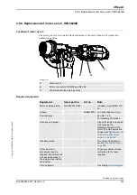
Removal, motor axis 4
The procedure below details how to remove the motor, axis 4.
Calibration
Pendulum toolkit
3HAC15716-1
Complete kit that also
includes operating manual.
Other tools and
procedures may be
required. See
references to these
procedures in the
step-by-step
instructions below.
These procedures include
references to the tools
required.
Circuit Diagram
3HAC025744-001
See chapter
Circuit diagram
.
Equipment, etc.
Spare part no.
Art. no.
Note
Action
Note
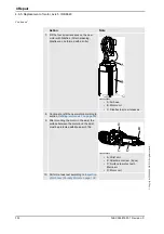
1. Move the robot to a position where the upper
arm is pointed straight up.
This position enables the motor to be
replaced without draining the gear oil, which
in turn saves time.
Any other position of the upper arm requires
a draining of oil from the gearbox for axis 4.
Draining of oil is described in section
2.
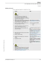
DANGER!
Turn off all electric power, hydraulic and
pneumatic pressure supplies to the robot!
For Foundry Prime robots: Do not turn off the
air pressure to motors and SMB.
3. Remove the cable gland cover at the cable
exit of the motor by unscrewing its two
attachment screws.
.
Make sure the gasket is not damaged!
4. Remove the cover on top of the motor by
unscrewing its four attachment screws.
5. Disconnect all connectors beneath the
motor cover.
6. In order to release the brake, connect the 24
VDC power supply.
Connect to connector R2.MP4
•
+: pin 2
•
-: pin 5
7. Unscrew the motors four attachment screws
and plain washers.
.
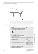
8. Fit the two guide pins in two of the motor
attachment screw holes.
9. If required, press the motor out of position by
fitting removal tool, motor to the motor
attachment screw holes.
Always use the removal tools in pairs!
Continued
Continues on next page


