


Repairs
Calibration
Product Manual IRB 640
49
14. Move the sensor and continue the calibration procedure for the other axes.
15. When all the axes have been adjusted, the resolver values are stored by executing
the following commands on the teach pendant.
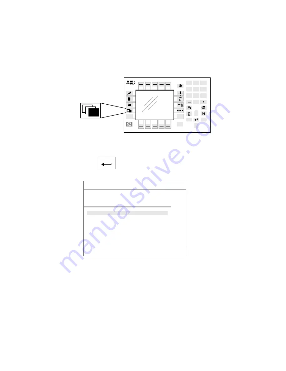
16. Press the Misc. window key (see Figure 13).
Figure 13 The Misc. window key from which the Service window can be selected
17. Select Service in the dialog box shown on the display.
18. Press Enter
.
19. Select View: Calibration. The window in Figure 14 appears.
Figure 14 The window shows whether or not the robot system units are calibrated.
The calibration status can be any of the following:
- Synchronised
All axes are calibrated and their positions are known. The unit is ready for use.
- Not updated Rev. Counter
All axes are fine-calibrated but one (or more) of the axes has a counter that is
NOT updated. That axis, or those axes, must therefore be updated as
described in Chapter 9.4, Setting the calibration marks on the manipulator.
2
1
2
3
0
1
4
5
6
7
8
9
P3
P1
P2
File
Edit
View
Calib
1(1)
Service Calibration
Unit
Status
Robot
Not Calibrated
Summary of Contents for IRB 640
Page 1: ...Product Manual 3HAC 7579 1 IRB 640 M2000 ...
Page 4: ...Installation and Commissioning Page 2 Product Manual IRB 640 ...
Page 19: ...Installation and Commissioning On Site Installation Product Manual IRB 640 17 ...
Page 20: ...On Site Installation Installation and Commissioning 18 Product Manual IRB 640 ...
Page 29: ...Maintenance CONTENTS Page 2 Product Manual IRB 640 ...
Page 69: ...Axis 2 Repairs 26 Product Manual IRB 640 ...
Page 79: ...Link system Repairs 36 Product Manual IRB 640 ...
Page 81: ...Pushbutton unit for releasing brakes Repairs 38 Product Manual IRB 640 ...
Page 85: ...Axis 6 Repairs 42 Product Manual IRB 640 ...
Page 101: ...Calibration Repairs 58 Product Manual IRB 640 ...
Page 105: ...Special Tools List Repairs 62 Product Manual IRB 640 ...
Page 122: ......
Page 123: ......
Page 124: ......
Page 125: ......
Page 126: ......
Page 127: ......
Page 128: ......
Page 129: ......
Page 130: ......
Page 131: ......
Page 132: ......
Page 133: ......
Page 134: ......
Page 135: ......
Page 136: ......
Page 137: ......
Page 138: ......
Page 139: ......
Page 140: ......
Page 142: ...Circuit Diagram Page 2 Product Manual S4Cplus ...
Page 143: ...Revision 00 No of sheets sheet 3 10 Circuit Diagram 3HAC 1352 1 Contents ...
Page 144: ...Revision 00 No of sheets sheet 4 10 Circuit Diagram 3HAC 1352 1 Connection Point Location ...
Page 145: ...Revision 00 No of sheets sheet 5 10 Circuit Diagram 3HAC 1352 1 Legend ...
Page 146: ...Revision 00 No of sheets sheet 6 10 Circuit Diagram 3HAC 1352 1 Brake Unit ...
Page 147: ...Revision 00 No of sheets sheet 7 10 Circuit Diagram 3HAC 1352 1 Axis 1 ...
Page 148: ...Revision 00 No of sheets sheet 8 10 Circuit Diagram 3HAC 1352 1 Axis 2 ...
Page 149: ...Revision 00 No of sheets sheet 9 10 Circuit Diagram 3HAC 1352 1 Axis 3 ...
Page 150: ...Revision 00 No of sheets sheet 10 10 Circuit Diagram 3HAC 1352 1 Axis 6 ...
Page 152: ...Revision 00 No of sheets sheet 12 10 Circuit Diagram 3HAC 1352 1 Customer Signal Connection ...


