background image

KNX Technical Reference Manual 


ABB-i-Bus

®

-KNX Millenium 


Safety


KNX Technical Reference Manual | 1473-1-8681 

— 9 —


Pos: 9.1 /Layout bis 2014-11-11/Online-Dokumentation (+KNX)/Überschriften (--> Für alle Dokumente <--)/1. Ebene/S - T/Sicherheit @ 18\mod_1302612791790_15.docx @ 103357 @ 2 @ 1 


Safety 


Pos: 9.2 /Layout bis 2014-11-11/Online-Dokumentation (+KNX)/Sicherheitshinweise und Hinweise (--> Für alle Dokumente <--)/Warnhinweise/Sicherheit - 230 V @ 18\mod_1302606816750_15.docx @ 103308 @  @ 1 


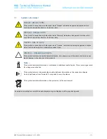
Warning 

Electric voltage! 

Risk of death and fire due to electrical voltage of 230 V. 
–  Work on the 230V supply system may only be performed by authorised electricians! 
–  Disconnect the mains power supply prior to installation and/or disassembly! 


Pos: 9.3 /Layout bis 2014-11-11/Online-Dokumentation (+KNX)/Sicherheitshinweise und Hinweise (--> Für alle Dokumente <--)/Hinweise - Sachschäden/Achtung - Beschädigung durch äußere Einwirkungen @ 26\mod_1343995985123_15.docx @ 226743 @  @ 1 


Caution 

Risk of damaging the device due to external factors! 

Moisture and contamination can damage the device. 
That is why the device must be protected against humidity, dirt and damage during transport, 
storage and operation! 


Pos: 9.4.1 /Layout bis 2014-11-11/Online-Dokumentation (+KNX)/Überschriften (--> Für alle Dokumente <--)/2. Ebene/A - F/Bestimmungsgemäßer Gebrauch @ 25\mod_1340691838858_15.docx @ 220036 @ 2 @ 1 


2.1 

Intended use 


Pos: 9.4.2 /Layout bis 2014-11-11/Online-Dokumentation (+KNX)/Sicherheit/KNX/KNX-Sensorik/Millenium/6124 - Raumtemperaturregler/Bestimmungsgemäßer Gebrauch/Bestimmungsgemäßer Gebrauch @ 30\mod_1348492387307_15.docx @ 238854 @  @ 1 


The device must only be operated within the specified technical data! 
The room temperature controller is suitable for the control of a ventilator convector with a fan-coil actuator or a 
conventional heating and cooling system. Extensive functions are available for the room temperature controller. 
The scope of the application is contained in chapter "Application ..." (only in languages of the countries DE, EN, 
ES, FR, IT and NL). The integrated bus coupler makes possible the connection of a KNX bus line. 


Note 

They may only be installed in dry interior rooms in flush-mounted sockets according to 
BS 4662:2006+A1:2009. 


Pos: 9.5.1 /Layout bis 2014-11-11/Online-Dokumentation (+KNX)/Überschriften (--> Für alle Dokumente <--)/2. Ebene/A - F/Bestimmungswidriger Gebrauch @ 30\mod_1348482382253_15.docx @ 238583 @ 2 @ 1 


2.2 

Improper use 


Pos: 9.5.2 /Layout bis 2014-11-11/Online-Dokumentation (+KNX)/Sicherheit/KNX/KNX-Sensorik/Millenium/6122 - Busch-Wächter 180°/Bestimmungswidriger Gebrauch/Bestimmungswidriger Gebrauch @ 30\mod_1348219750451_15.docx @ 237704 @  @ 1 


The device represents a danger if it is improperly used. Each non-intended use is deemed improper use. The 
manufacturer is not liable for damages resulting from such improper use. The associated risk is borne by the 
user/operator. 
The device must never be used outdoors or in bathroom areas. Do not push objects through the openings in the 
device. The device has an integrated bus coupler. The use of an additional bus coupler is therefore not 
admissible. 


Pos: 9.6 /Layout bis 2014-11-11/Online-Dokumentation (+KNX)/Steuermodule - Online-Dokumentation (--> Für alle Dokumente <--)/++++++++++++ Seitenu+++++++++++ @ 9\mod_1268898668093_0.docx @ 52149 @  @ 1 


Summary of Contents for -i-Bus-KNX Millenium

Page 1: ... Millenium Pos 2 Layout bis 2014 11 11 Online Dokumentation KNX Titelblätter KNX KNX Sensorik Millenium Titelblatt 6124 20 xxx ABB B2C Concept 40 mod_1421830160972_15 docx 314508 1 Room temperature controller incl BAU 6124 08 981 500 Ende der Liste für Textmarke Cover ...

Page 2: ...ion of installation site 16 6 3 Mounting 18 6 3 1 Installing the unit 18 6 4 7Electrical connection 19 7 Commissioning 20 7 1 Software 20 7 1 1 Preparatory steps 20 7 1 2 Assigning a physical address 20 7 1 3 Assigning the group address es 21 7 1 4 Selecting the application program 21 7 1 5 Differentiating the application program 21 8 Operation 22 8 1 Overview of control elements 22 8 2 Indication...

Page 3: ...emperature difference to basic stage x 0 1 C 40 11 3 27 Control of additional heating stage Extended settings 40 11 3 28 Additional heating stage 40 11 3 29 Additional heating stage Mode of the control value 40 11 3 30 Additional heating stage Hysteresis x 0 1 C 41 11 3 31 Additional heating stage Control value difference for sending of heating control value 41 11 3 32 Additional heating stage Cyc...

Page 4: ...of the current set point temperature min 58 11 3 83 Setpoint adjustment 58 11 3 84 Setpoint adjustment Maximum manual increase during heating mode 0 15 C 58 11 3 85 Setpoint adjustment Maximum manual reduction during heating mode 0 15 C 58 11 3 86 Setpoint adjustment Maximum manual increase during cooling mode 0 15 C 59 11 3 87 Setpoint adjustment Maximum manual reduction during cooling mode 0 15 ...

Page 5: ...xit from summer compensation x 0 1 C 70 11 4 Additional Millennium RTC Application Control settings 71 11 4 1 General Jump back to the primary function 71 11 4 2 Temperature display Temperature unit 71 11 4 3 General Setting the temperature unit via object 71 11 4 4 General Setpoint display 71 11 4 5 General Display of actual temperature 71 11 4 6 General Waiting period for display of actual tempe...

Page 6: ...nfirm fan speed level 87 11 5 45 Controller status RHCC 88 11 5 46 Controller status HVAC 88 11 5 47 Commissioned 88 11 6 Additional Millennium RTC Communication objects Control settings 89 11 6 1 Day Night mode 89 11 7 Applications for Button top right 90 11 7 1 Application 1 button switching 90 11 7 2 Application 1 button dimming 90 11 7 3 Application 2 button value transmitter 91 11 7 4 Applica...

Page 7: ...l must be observed and adhered to Modifications and repairs to the product must only be undertaken if the manual expressly permits this It is only the adherence to the safety instructions and all safety and warning symbols in this manual that will ensure the optimum protection of the user and the environment as well as the safe and trouble free operation of the product Pos 7 3 1 Layout bis 2014 11...

Page 8: ...situation which could lead to immediate death or to serious injury Caution risk of injury This symbol in connection with the signal word Caution indicates a possibly dangerous situation which could lead to slight or moderately serious injury Attention damage to property This symbol indicates a possibly harmful situation Non observance of the safety instructions can lead to damage or destruction of...

Page 9: ...emäßer Gebrauch 30 mod_1348492387307_15 docx 238854 1 The device must only be operated within the specified technical data The room temperature controller is suitable for the control of a ventilator convector with a fan coil actuator or a conventional heating and cooling system Extensive functions are available for the room temperature controller The scope of the application is contained in chapte...

Page 10: ...authorized modification excludes the liability of the manufacturer for the damages caused It voids the warranty of the manufacturer Pos 9 9 1 Layout bis 2014 11 11 Online Dokumentation KNX Überschriften Für alle Dokumente 2 Ebene U Z Umwelt 25 mod_1340691935719_15 docx 220064 2 1 2 5 Environment Pos 9 9 2 Layout bis 2014 11 11 Online Dokumentation KNX Sicherheitshinweise und Hinweise Für alle Doku...

Page 11: ...ect access to the room temperature controller via KNX and activate controllers in the room The fan speed level can also be selected manually via a buttons forced operation This makes it possible to very quickly adjust the temperature in a hotel room to the individual wishes of the guests The device supports the full function for international hotel applications It can function in the operating mod...

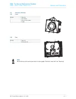
Page 12: ...Dokumentation KNX Aufbau und Funktion KNX KNX Sensorik Millenium 6124 Raumtemperaturregler Geräteübersicht 6124 26 mod_1343982815048_15 docx 226687 33 1 3 2 1 Front Position Function 1 Push buttons 2 Rotary control element 3 Display 3 2 2 Rear Position Function 1 KNX connection Note Observe the special mounting instructions in paragraphs Electrical connection and Mounting Pos 11 7 Layout bis 2014 ...

Page 13: ...Layout bis 2014 11 11 Online Dokumentation KNX Aufbau und Funktion KNX KNX Sensorik Millenium 6122 Busch Wächter 180 Abdeckrahmen und Tragring 6122 31 mod_1348833939342_15 docx 240513 1 Note A cover frame and a support ring from the Millenium program are additionally required see the following illustration These must be ordered separately Fig 1 Cover frame and support ring Pos 13 Layout bis 2014 1...

Page 14: ...A F Anschluss und Maßbilder 24 mod_1338553942062_15 docx 215314 1 1 5 Circuit diagrams and dimensional drawings Pos 15 2 Layout bis 2014 11 11 Online Dokumentation KNX Überschriften Für alle Dokumente 2 Ebene A F Anschlussbild 31 mod_1348834725144_15 docx 240563 2 1 5 1 Circuit diagram Pos 15 3 Layout bis 2014 11 11 Online Dokumentation KNX Montage und elektrischer Anschluss KNX KNX Sensorik Mille...

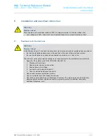
Page 15: ...se 23 mod_1336559183027_15 docx 209179 2 1 6 1 Requirements for the electrician Warning Electric voltage Install the device only if you have the necessary electrical engineering knowledge and experience Incorrect installation endangers your life and that of the user of the electrical system Incorrect installation can cause serious damage to property e g due to fire The minimum necessary expert kno...

Page 16: ...egler Auswahl des Montageortes 26 mod_1343988571510_15 docx 226701 1 For proper commissioning please observe the following steps The room temperature controller should be installed at a height of approximately 150 cm from the floor and 50 cm from a door frame The room temperature controller should be installed on a wall opposite a radiator The angles of room architecture should not separate a radi...

Page 17: ... room temperature controller with fluids is to be avoided Just as heat radiated from electric loads can impair the temperature regulation so can direct sunlight on the room temperature controller Pos 18 7 Layout bis 2014 11 11 Online Dokumentation KNX Steuermodule Online Dokumentation Für alle Dokumente Seitenumbruch 9 mod_1268898668093_0 docx 52149 1 ...

Page 18: ...ing in flush mounted boxes according to BS 4662 2006 A1 2009 in connection with the corresponding support ring and cover frame see also chapter Cover frame and support ring on page 13 1 The side of the support ring with the marking TOP must be aligned toward the top Now insert the device into the support ring in such a way that both sides with the marking TOP on the device and the support ring are...

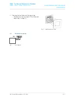
Page 19: ... Dokumentation KNX Überschriften Für alle Dokumente 2 Ebene A F Elektrischer Anschluss 21 mod_1328177051724_15 docx 138042 2 1 6 4 7Electrical connection Pos 18 11 Layout bis 2014 11 11 Online Dokumentation KNX Montage und elektrischer Anschluss KNX KNX Sensorik Millenium 6122 Busch Wächter 180 Anschlussbild xxxx 26 mod_1344333399173_15 docx 226944 1 Fig 7 Circuit diagram Pos 20 Layout bis 2014 11...

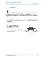
Page 20: ...Arbeitsschritte 31 mod_1351084403550_15 docx 243607 3 1 7 1 1 Preparatory steps Pos 21 5 Layout bis 2014 11 11 Online Dokumentation KNX Inbetriebnahme KNX KNX Sensorik Millenium 6122 Busch Wächter 180 Inbetriebnahme Software Vorber Arbeitsschritte 6124 40 mod_1421843968920_15 docx 314637 1 1 Connect a PC via the KNX interface e g the commissioning interface adapter 6149 21 500 to the KNX bus line ...

Page 21: ...Inbetriebnahme KNX KNX Sensorik Millenium 6122 Busch Wächter 180 Inbetriebnahme Software Anwendungsprogramm wählen 31 mod_1351084192233_15 docx 243593 1 Please contact our Internet support unit www Busch Jaeger com The application is loaded into the device via the ETS Pos 21 13 Layout bis 2014 11 11 Online Dokumentation KNX Überschriften Für alle Dokumente 3 Ebene A F Anwendungsprogramm differenzi...

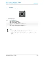
Page 22: ...ig 9 Control and display elements Position Control display elements 1 Button for selecting the fan speed level 2 Rotary control element setpoint adjustment 3 Button function is freely parameterizable switching dimming etc 4 Button for activating the ECO mode e g during your absence 5 Display 6 Button for activating deactivating the room temperature controller Note The basic setting of the display ...

Page 23: ...om temperature controller is deactivated Eco mode Alarm Frost protection heat protection Condensate Standby mode Dew point Nighttime temperature reduction 8 3 LED colour concept 8 3 1 Explanation Colour Meaning White Set point temperature actual temperature Blue Set point temperature actual temperature Orange Set point temperature actual temperature Green Eco mode White Alarms and operating modes ...

Page 24: ...ng the rotary control element see also Fig 9 The functions of the buttons in connection with the rotary control element and the display are described in the following The precise function is fixed via the assigned application function and their parameter settings Extensive applications are available for the room temperature controller see the overview of the applications at the beginning of chapte...

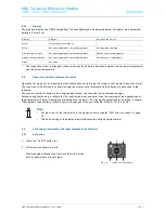
Page 25: ...ntrol element is actuated the set point temperature is shown in the display If the set point temperature is unequal to the actual temperature each change is indicated in the display from white to orange or blue Here the background becomes correspondingly coloured and the display black 1 Turn the rotary control element 2 for the setpoint adjustment to the right warmer to the left colder Observe the...

Page 26: ... time expires The adjustment is stored After the set time or when the rotary control element is actuated the device changes back to the Setpoint adjustment Fig 13 Device in fan speed level setting If button Fan speed levels 1 is actuated the currently set fan speed level or the corresponding operating status appears in the display Automatic ventilation display of fan speed level plus A Ventilation...

Page 27: ...t were active prior to the activation of ECO mode Fig 14 Device in ECO mode Note During ECO mode the temperature cannot for example be adjusted manually The function and setting of ECO mode is adjustable via parameters The default setting can not be adjusted via the rotary control element 8 9 Individual button function The button 3 can be individually programmed with abutton function Operation is ...

Page 28: ...re reduction The temperature can be reduced during the night This saves energy and makes the night s rest comfortable The heating starts again automatically the next morning to reach a comfortable temperature for rising Frost protection If parameterized frost protection will ensure that the temperature does not drop below the desired value It is the lowest setpoint Heat protection If parameterized...

Page 29: ...Caustic cleaning agents or solvents must not be used Pos 28 1 Layout bis 2014 11 11 Online Dokumentation KNX Überschriften Für alle Dokumente 1 Ebene U Z Wartung 21 mod_1328188606500_15 docx 138248 1 1 10 Maintenance Pos 28 2 Layout bis 2014 11 11 Online Dokumentation KNX Wartung KNX KNX Sensorik MilleniumWartung 26 mod_1344333514582_15 docx 226958 1 The unit is maintenance free In case of damage ...

Page 30: ... Application program Continuous switching heating cooling TP 7 Pos 31 4 Layout bis 2014 11 11 Online Dokumentation KNX Überschriften Für alle Dokumente 2 Ebene A F Anwendungs Applikations programm 41 mod_1421851906124_15 docx 314749 2 1 11 2 Application program Pos 31 5 Layout bis 2014 11 11 Online Dokumentation KNX Applikations Objektbeschreibungen KNX KNX Sensorik Millenium 6124 Raumtemperaturre...

Page 31: ...ne Applikations Parameterbeschreibungen KNX Applikation Objekt RTR ModuleAllgemein Reglerfunktion 40 mod_1421678818959_15 docx 312408 3 1 11 3 2 General Control function Options Heating Heating with additional stage Cooling Cooling with additional stage Heating and cooling Heating and cooling with additional stage Heating For operating a heat based automatic single room control The temperature is ...

Page 32: ...e may be This operating mode should be defined during the planning phase An improperly defined operating mode can result in a loss of comfort or increased energy consumption Comfort If the room temperature is not automatically lowered and the room is therefore controlled independent of its use Standby If the room is controlled automatically e g by a presence detector as a function of its use Eco m...

Page 33: ...e Options 2 point 1 bit Off On 2 point 1 byte 0 100 PI continuous 0 100 PI PWM On Off Fan coil The actuation of the control valve is determined by the selection of the controller type 2 Point 1 Bit Off On The 2 point control is the simplest type of control The controller switches on when the room temperature drops below a certain level setpoint temperature value minus hysteresis and switches off w...

Page 34: ...tpoint value and can be used to influence control speed with a PI controller The smaller the setpoint the faster it reacts to the control However to avoid the risk of an overshoot this value should not be set too low A P component from 0 1 to 25 5 K can be set Note This parameter is only available when Control value type parameter is set either on PI continuous 0 100 PI PWM On Off or Fan coil In a...

Page 35: ...s No Yes This parameter enables the Status heating communication object Pos 31 7 17 DinA 4 Online Applikations Parameterbeschreibungen KNX Applikation Objekt RTR ModuleGrundstufe Heizen Wirksinn der Stellgröße 40 mod_1421680138767_15 docx 312588 3 1 11 3 14 Basic stage heating Mode of the control value Options Normal Inverse The mode of the control value can be used to adapt the control value to d...

Page 36: ...the previous sent value to make a transmission meaningful This value difference can be entered here Note This parameter is only available when Control value type parameter is set either on PI continuous 0 100 PI PWM On Off or Fan coil Pos 31 7 20 DinA 4 Online Applikations Parameterbeschreibungen KNX Applikation Objekt RTR ModuleGrundstufe Heizen Zyklisches Senden der Stellgröße min 40 mod_1421680...

Page 37: ...only available when Control value type parameter is set either on PI continuous 0 100 PI PWM On Off or Fan coil Pos 31 7 24 DinA 4 Online Applikations Parameterbeschreibungen KNX Applikation Objekt RTR ModuleGrundstufe Heizen Grundlast min Stellgröße 0 255 40 mod_1421680539734_15 docx 312678 3 1 11 3 20 Basic stage heating Minimum control value for basic load 0 to 255 Options Setting option betwee...

Page 38: ...itted as 1 bit commands 2 Point 1 Byte 0 100 This is another two point control as described above In this case however the switch on and switch off commands are transmitted as 1 byte values 0 100 PI continuous 0 100 The PI controller adjusts its output value between 0 and 100 to match the difference between the actual value and the setpoint value and enables a precise regulation of the room temper...

Page 39: ...ilable when Control value type parameter is set either on PI continuous 0 100 PI PWM On Off or Fan coil Pos 31 7 29 DinA 4 Online Applikations Parameterbeschreibungen KNX Applikation Objekt RTR ModuleRegelung Zusatzstufe Heizen P Anteil x 0 1 C 40 mod_1421680905289_15 docx 312738 3 1 11 3 24 Control of additional heating stage P component x 0 1 C Options Setting option between 10 100 The P compone...

Page 40: ...o basic stage x 0 1 C Options Setting option between 0 255 The setpoint temperature of the additional stage is defined as a function of the current setpoint temperature of the base stage and is expressed as a difference The value represents the setpoint value starting at which the additional stage will operate Pos 31 7 33 DinA 4 Online Applikations Parameterbeschreibungen KNX Applikation Objekt RT...

Page 41: ...arameter is set either on 2 point 1 Bit Off On or 2 point 1 Byte 0 100 Pos 31 7 37 DinA 4 Online Applikations Parameterbeschreibungen KNX Applikation Objekt RTR ModuleZusatzstufe Heizen Stellgrößendifferenz für Senden der Stellgröße Heizen 40 mod_1421681431586_15 docx 312843 3 1 11 3 31 Additional heating stage Control value difference for sending of heating control value Options 2 5 10 Send cycli...

Page 42: ...ailable when Control value type parameter is set either on PI continuous 0 100 PI PWM On Off or Fan coil Pos 31 7 40 DinA 4 Online Applikations Parameterbeschreibungen KNX Applikation Objekt RTR ModuleZusatzstufe Heizen Grundlast min Stellgröße 0 255 40 mod_1421681560021_15 docx 312873 3 1 11 3 33 Additional heating stage Minimum control value for basic load 0 255 Options Setting option between 0 ...

Page 43: ...ertain level setpoint temperature value minus hysteresis and switches off when a particular value setpoint temperature value plus hysteresis is exceeded The switch on and switch off commands are transmitted as 1 bit commands 2 Point 1 Byte 0 100 This is another two point control as described above In this case however the switch on and switch off commands are transmitted as 1 byte values 0 100 PI ...

Page 44: ...tional band of a control It fluctuates around the setpoint value and can be used to influence control speed with a PI controller The smaller the setpoint the faster it reacts to the control However to avoid the risk of an overshoot this value should not be set too low A P component from 0 1 to 25 5 K can be set Note This parameter is only available when Control value type parameter is set either o...

Page 45: ...te Only available when the Extended settings parameter under Cooling control is set on Yes Pos 31 7 50 DinA 4 Online Applikations Parameterbeschreibungen KNX Applikation Objekt RTR ModuleGrundstufe Kühlen Statusobjekt Kühlen 40 mod_1421682228449_15 docx 312993 3 1 11 3 41 Basic stage cooling Status object cooling Options No Yes This parameter enables the Status cooling communication object Pos 31 ...

Page 46: ...nd cyclic only The control values of the 0 100 PI continuous controller are not transmitted after every calculation Instead they are transmitted when the calculation results in a value that is different enough to the previous sent value to make a transmission meaningful This value difference can be entered here Note This parameter is only available when Control value type parameter is set either o...

Page 47: ...putted by the controller If a maximum value under 255 is chosen the value will not be exceeded even if the controller calculates a higher control value Note This parameter is only available when Control value type parameter is set either on PI continuous 0 100 PI PWM On Off or Fan coil Pos 31 7 57 DinA 4 Online Applikations Parameterbeschreibungen KNX Applikation Objekt RTR ModuleGrundstufe Kühlen...

Page 48: ...t temperature value plus hysteresis is exceeded The switch on and switch off commands are transmitted as 1 bit commands 2 Point 1 Byte 0 100 This is another two point control as described above In this case however the switch on and switch off commands are transmitted as 1 byte values 0 100 PI continuous 0 100 The PI controller adjusts its output value between 0 and 100 to match the difference bet...

Page 49: ...fers to the proportional band of a control It fluctuates around the setpoint value and can be used to influence control speed with a PI controller The smaller the setpoint the faster it reacts to the control However to avoid the risk of an overshoot this value should not be set too low A P component from 0 1 to 25 5 K can be set Note This parameter is only available when Control value type paramet...

Page 50: ...dule Zusatzstufe Kühlen Wirksinn der Stellgröße 40 mod_1421738600834_15 docx 313243 3 1 11 3 54 Additional cooling stage Mode of the control value Options Normal Inverse The mode of the control value can be used to adapt the control value to de energised opened normal or de energised closed inverse valves Normal Value 0 means Valve closed Inverse Value 0 means Valve open Pos 31 7 67 DinA 4 Online ...

Page 51: ...dule Zusatzstufe Kühlen Zyklisches Senden der Stellgröße min 40 mod_1421739480045_15 docx 313304 3 1 11 3 57 Additional cooling stage Cyclic sending of the control value min Options Setting option between 1 60 minutes The current control value used by the device can be cyclically transmitted to the bus Note This parameter is only available when the Control value type parameter is set either on 2 p...

Page 52: ...stage Cooling with additional stage Heating and cooling or Heating and cooling with additional stages Pos 31 7 75 DinA 4 Online Applikations Parameterbeschreibungen KNX Applikation Objekt RTR Module Einstellungen Grundlast Grundlast min Stellgröße 0 40 mod_1421740733550_15 docx 313364 3 1 11 3 61 Settings of basic load Minimum control value for basic load 0 Options Always active Activate via objec...

Page 53: ...and to the associated setpoint is carried out manually on the device by the user of the room or via the Switchover heating cooling object via the bus Switchover heating cooling is a transmitting and receiving object Pos 31 7 79 DinA 4 Online Applikations Parameterbeschreibungen KNX Applikation Objekt RTR Module Kombinierter Heiz und Kühlbetrieb Betriebsart nach Reset 40 mod_1421741049154_15 docx 3...

Page 54: ...rteinstellungen 40 mod_1421741365616_15 docx 313454 3 1 11 3 67 Setpoint settings Note This parameter is only available if the Device function parameter is set on either Single device or Master device Pos 31 7 84 DinA 4 Online Applikations Parameterbeschreibungen KNX Applikation Objekt RTR Module Sollwerteinstellungen Sollwert Heizen Komfort Sollwert Kühlen Komfort 40 mod_1421741414381_15 docx 313...

Page 55: ... C Options Setting option between 10 40 Specifies the comfort temperature for heating and cooling when people are present Note This parameter is only available when the Control function parameter is set on Heating and cooling or heating and cooling with additional stages Pos 31 7 88 DinA 4 Online Applikations Parameterbeschreibungen KNX Applikation Objekt RTR Module Sollwerteinstellungen Solltempe...

Page 56: ... on Heating Heating with additional stage Heating and cooling or Heating and cooling with additional stages Pos 31 7 93 DinA 4 Online Applikations Parameterbeschreibungen KNX Applikation Objekt RTR Module Sollwerteinstellungen Solltemperatur Komfort Kühlen C 40 mod_1421741954266_15 docx 313574 3 1 11 3 75 Setpoint settings Setpoint temperature for cooling comfort C Options Setting option between 1...

Page 57: ...on is blocked Note This parameter is only available when the Control function parameter is set on Cooling Cooling with additional stage Heating and cooling or Heating and cooling with additional stages Pos 31 7 98 DinA 4 Online Applikations Parameterbeschreibungen KNX Applikation Objekt RTR Module Sollwerteinstellungen Displayanzeige zeigt 40 mod_1421742653583_15 docx 313634 3 1 11 3 79 Setpoint s...

Page 58: ...jekt RTR Module Sollwertverstellung 40 mod_1421743359507_15 docx 313679 3 1 11 3 83 Setpoint adjustment Note This parameter is only available if the Device function parameter is set on either Single device or Master device Pos 31 7 104 DinA 4 Online Applikations Parameterbeschreibungen KNX Applikation Objekt RTR Module Sollwertverstellung max manuelle Anhebung beim Heizbetrieb 0 15 C 40 mod_142174...

Page 59: ... mode 0 15 C Options Setting option between 0 15 This preset can be used to limit the manual decrease during cooling Note This parameter is only available when the Control function parameter is set on Cooling Cooling with additional stage Heating and cooling or Heating and cooling with additional stages Pos 31 7 108 DinA 4 Online Applikations Parameterbeschreibungen KNX Applikation Objekt RTR Modu...

Page 60: ...Verstellung über Objekt 40 mod_1421744043574_15 docx 313784 3 1 11 3 90 Setpoint adjustment Resetting the manual adjustment via object Options No Yes If this parameter is activated a separate object can be used to delete the manual adjustment at any time Example of application Resetting the manual adjustment on all devices located in a building using a system clock Pos 31 7 112 DinA 4 Online Appli...

Page 61: ...hted temperature reading parameter is set on Internal and external measurement or Internal and 2x external measurement Pos 31 7 117 DinA 4 Online Applikations Parameterbeschreibungen KNX Applikation Objekt RTR Module Temperaturerfassung Gewichtung der externen Messung 0 100 40 mod_1421744895847_15 docx 313859 3 1 11 3 95 Temperature reading Weighting of external measurement 0 to 100 Options Settin...

Page 62: ...tion location has different physical conditions interior or exterior wall lightweight or solid wall etc In order to use the actual temperature at the installation location as a measured value for the device a temperature measurement must be performed by an external equalised and or calibrated thermometer at the installation location The difference between the actual temperature displayed on the de...

Page 63: ...ting the building will be selected Pos 31 7 127 DinA 4 Online Applikations Parameterbeschreibungen KNX Applikation Objekt RTR Module Alarmfunktionen 40 mod_1421745673649_15 docx 313979 3 1 11 3 103 Alarm functions Note This parameter is only available if the Device function parameter is set on either Single device or Master device Pos 31 7 128 DinA 4 Online Applikations Parameterbeschreibungen KNX...

Page 64: ...jects have a frost alarm bit It the input temperature of the controller drops below the temperature set in this parameter then the frost alarm bit is set in the status objects It is reset when the temperature is exceeded Pos 31 7 132 DinA 4 Online Applikations Parameterbeschreibungen KNX Applikation Objekt RTR Module Alarmfunktionen Temperatur Hitzealarm RHCC Status C 40 mod_1421745946645_15 docx ...

Page 65: ...arameterbeschreibungen KNX Applikation Objekt RTR Module Fancoil Einstellungen Lüfterstufen Stufenausgabe 40 mod_1421746237446_15 docx 314099 3 1 11 3 111 Fan coil settings Fan speed levels Level output Options For manual operation and automatic Only for manual operation This parameter is used to specify when the output of the fan speed level values will occur either only when the fan speed levels...

Page 66: ...ional stages Pos 31 7 141 DinA 4 Online Applikations Parameterbeschreibungen KNX Applikation Objekt RTR Module Fancoil Einstellungen Heizen Lüfterstufe 1 5 bis Stellgröße 0 255 Heizen 40 mod_1421746567638_15 docx 314159 3 1 11 3 115 Fan coil settings for heating Speed level 1 to 5 up to control value 0 to 255 heating Options Setting option between 0 255 In this parameter the control values of the ...

Page 67: ...nment is used if the fan speed levels are transmitted together with the control values Note These level settings should be adjusted to match the settings in the fan coil actuator Setting the Control value type to Fan coil in the control parameters is only useful for one of either the basic stage or the additional stage Setting the basic and additional stage parameters to fan coil is not useful sin...

Page 68: ...side temperature value for summer compensation Upper outside temperature value for summer compensation Lower setpoint offset for summer compensation Upper setpoint offset for summer compensation Above the Upper outside temperature value the minimum setpoint temperature for cooling is the outside temperature minus the Upper setpoint offset The outside temperature has no effect on the minimum setpoi...

Page 69: ...ature for the entry into summer compensation x 0 1 C Options Setting option between 127 127 The parameter is used to define how many degrees Kelvin the setpoint value will be increased by during summer compensation when the lower temperature value is reached Typical values for summer compensation are 20 C Lower outside temperature value 32 C Upper outside temperature value 0 K Lower setpoint offse...

Page 70: ...n 127 127 The parameter is used to define how many degrees Kelvin the setpoint value will be increased by during summer compensation when the upper temperature value is reached Typical values for summer compensation are 20 C Lower outside temperature value 32 C Upper outside temperature value 0 K Lower setpoint offset 4 K Upper setpoint offset That means that a flowing setpoint increase of 0 to 4 ...

Page 71: ...renheit F Pos 31 9 4 DinA 4 Online Applikations Parameterbeschreibungen KNX Applikation Zusatz Millennium RTR Module Temperaturanzeige Einstellung der Temperatureinheit über Objekt 41 mod_1422466137443_15 docx 330603 3 1 11 4 3 General Setting the temperature unit via object Options No Yes The parameter is used to define whether the temperature unit adjustment is transmitted via an object Pos 31 9...

Page 72: ... control element the display changes to the setpoint adjustment After non actuation of the device the current actual temperature again appears in the display after the set waiting period Pos 31 9 9 DinA 4 Online Applikations Parameterbeschreibungen KNX Applikation Zusatz Millennium RTR Module Helligkeitseinstellung Tag Nachtbetrieb 41 mod_1422467762563_15 docx 330683 3 1 11 4 8 Brightness setting ...

Page 73: ...e green If the colour concept is not required the display can be selected in black and white The display then does not indicate the specific statuses Heating Cooling Pos 31 9 12 DinA 4 Online Applikations Parameterbeschreibungen KNX Applikation Zusatz Millennium RTR Module Erweiterte Einstellungen Hinterleuchtung der Symbole 41 mod_1422468219960_15 docx 330731 3 1 11 4 11 Extended settings Backlig...

Page 74: ...x 329750 3 1 11 5 2 Additional heating stage Number Name Object function Data type 2 Additional heating stage additional heating cooling stage Output 1 Switching 2 Percent 0 to 100 Description 1 This object is used to operate a switching actuating drive e g a thermoelectric positioner that is controlled by a switching heating actuator 2 This object is used to control an actuating drive with a cont...

Page 75: ...tching 2 Control On Off master Output Switching 3 Control On Off slave Output Switching If a 0 telegram is received the controller switches to OFF mode and regulates the temperature to the setpoint value for frost heat protection When the controller is switched on again the remaining operating mode objects are queried in order to determine the new operating mode Note About item 2 During active ON ...

Page 76: ...ations Parameterbeschreibungen KNX Kommunikationsobjekte Objekt RTR RTR Module Störung Ist Temperatur 41 mod_1422461044836_15 docx 329862 3 1 11 5 9 Fault actual temperature Number Name Object function Data type 9 1 Fault actual temperature Output Switching 2 Fault actual temperature master Output Switching 3 Fault actual temperature slave Output Switching If one of the parameterized input tempera...

Page 77: ... mod_1422461261600_15 docx 329910 3 1 11 5 12 Operating mode Number Name Object function Data type 12 1 Operating mode Input output HVAC mode 2 Operating mode master Input output HVAC mode 3 Operating mode slave Input output HVAC mode The Operating mode object receives as a 1 byte value the operating mode that is to be set Here value 1 means Comfort value 2 Standby value 3 Economy and value 4 Fros...

Page 78: ...ster slave mode is active the Superimposed operating mode object of the master and the slave must be connected to the group address of the transmitter Pos 31 11 18 DinA 4 Online Applikations Parameterbeschreibungen KNX Kommunikationsobjekte Objekt RTR RTR Module Fensterkontakt 41 mod_1422461410317_15 docx 329942 3 1 11 5 14 Window contact Number Name Object function Data type 14 1 Window contact I...

Page 79: ... object of the master and the slave must be connected to the group address of the transmitter Pos 31 11 21 DinA 4 Online Applikations Parameterbeschreibungen KNX Kommunikationsobjekte Objekt RTR RTR Module Status Heizen 41 mod_1422461503076_15 docx 329974 3 1 11 5 16 Heating status Number Name Object function Data type 16 Heating status Output Switching The room temperature controller sends an ON ...

Page 80: ... Kommunikationsobjekte Objekt RTR RTR Module Umschaltung Heizen Kühlen 41 mod_1422461683726_15 docx 330022 3 1 11 5 19 Switchover heating cooling Number Name Object function Data type 17 Switchover heating cooling Input output Switching 1 Automatic If the switchover between heating and cooling is performed automatically by the room temperature controller then this object is used to provide informa...

Page 81: ...ode the fan coil manual slave object must be connected to this object Item 3 If fan coil manual is active in the master slave mode the fan coil manual master object must be connected to this object Pos 31 11 28 DinA 4 Online Applikations Parameterbeschreibungen KNX Kommunikationsobjekte Objekt RTR RTR Module Fancoil Stufe 41 mod_1422461829339_15 docx 330054 3 1 11 5 21 Fan coil step Number Name Ob...

Page 82: ...2 3 1 11 5 24 Fan speed level 2 Number Name Object function Data type 22 Fan speed level 2 Output Switching This 1 bit communication object is used to output the active status 1 of the fan speed level while the other fan speed levels are deactivated 0 depending on the parameter setting If the fan speed level is inactive the object has a value of 0 Pos 31 11 33 DinA 4 Online Applikations Parameterb...

Page 83: ...t heating comfort Setpoint cooling comfort or an average between heating and cooling comfort Pos 31 11 38 DinA 4 Online Applikations Parameterbeschreibungen KNX Kommunikationsobjekte Objekt RTR RTR Module Manuelle Sollwerte zurücksetzen 41 mod_1422462367202_15 docx 330182 3 1 11 5 29 Resetting manual setpoints Number Name Object function Data type 27 Resetting manual setpoints Input Switching This...

Page 84: ... value 0 When an alarm is active manual operation of the controller is blocked This information is indicated by a corresponding icon on the device When the master slave mode is active the condensate water alarm master slave objects must be connected to the alarm transmitter Pos 31 11 42 DinA 4 Online Applikations Parameterbeschreibungen KNX Kommunikationsobjekte Objekt RTR RTR Module Außentemperat...

Page 85: ...nt set on the device in comfort mode has been reached it is sent by means of value 1 as information to the KNX bus via the 1 bit communication object The function is started by activating the comfort or presence mode If the reaching of the setpoint temperature is interfered with by the preselection of a different operating mode or by adjustment to a new setpoint value 0 is sent Pos 31 11 46 DinA 4...

Page 86: ...onsobjekte Objekt RTR RTR Module Sollwertanzeige 41 mod_1422462896751_15 docx 330326 3 1 11 5 38 Setpoint display Number Name Object function Data type 36 1 Setpoint display master Input output 2 byte floating point value 2 Setpoint display slave Input output 2 byte floating point value This 2 byte communication object must be connected to the respective slave communication object in order to sync...

Page 87: ... be connected to the respective slave communication object in order to synchronise the devices in the master slave configuration Pos 31 11 55 DinA 4 Online Applikations Parameterbeschreibungen KNX Kommunikationsobjekte Objekt RTR RTR Module Lüfterstufe anfordern 41 mod_1422463241890_15 docx 330406 3 1 11 5 43 Request fan speed level Number Name Object function Data type 41 1 Request fan speed leve...

Page 88: ...HVAC Output Percent 0 100 2 Controller status HVAC master Output Percent 0 100 3 Controller status HVAC slave Output Percent 0 100 This communication object outputs the current operating mode the heating cooling mode active inactive mode the frost alarm and the dew point alarm in accordance with the specification for the HVAC Heating Ventilation Air Conditioning status Note Item 2 If the master sl...

Page 89: ...arameterbeschreibungen KNX Kommunikationsobjekte Zusatz Millennium RTR Module Tag Nachtbetrieb 41 mod_1422469024478_15 docx 330798 3 1 11 6 1 Day Night mode Number Name Object function Data type 47 Day Night mode Switching Description Via the activated communication object Day Night the backlighting of the display is shown bright during day mode and darker during night mode Note The operation only...

Page 90: ...e On Off alternating on off no reaction Objects No Object name Data type Flags 0 Switching 1 Bit EIS1 DPT 1 001 C W T U Pos 31 17 Layout bis 2014 11 11 Online Dokumentation KNX Applikations Objektbeschreibungen KNX KNX Sensorik Millenium 6125 26 29 IR Bedienelement Applikationen Bedienelement mit Multifunktion Applikation 1 Tasten Dimmen 41 mod_1422540166803_15 docx 331447 2 1 11 7 2 Application 1...

Page 91: ...General parameter Settings Comments Object type 1 bit 1 byte 0 100 1 byte 0 255 2 byte float 2 byte signed 2 byte unsigned 4 byte float 4 byte signed 4 byte unsigned Working mode of the buttons 1st button value 1 2nd button value 2 1st button value 2 2nd button value 1 alternating value1 value2 Value 1 For 1 bit On Off For 1 byte 0 100 0 100 For 1 byte 0 255 0 255 For 2 byte float 671088 6 670760 ...

Page 92: ...5 26 29 IR Bedienelement Applikationen Bedienelement mit Multifunktion Applikation 1 Tasten Wertsender 2 Objekte 41 mod_1422540190858_15 docx 331464 2 1 11 7 4 Application 1 button value transmitter 2 objects When actuating and or releasing the buttons two telegrams with predefined values are sent from two different communication objects In each case the application makes a separate set of paramet...

Page 93: ...lue 2 für 1 bit On Off für 1 byte 0 100 0 100 für 1 byte 0 255 0 255 für 2 byte float 671088 6 670760 9 für 2 byte signed 32768 32767 für 2 byte unsigned 0 65535 für 4 byte float 4000000 4000000 für 4 byte signed 2147483648 2147483647 für 4 byte unsigned 0 4294967295 Value 1 2 for falling edge Only available when parameter Reaction to falling edge is set on Alternating value 1 value 2 für 1 bit On...

Page 94: ... edge 4 byte float 4 Byte EIS9 DPT 14 xxx C W T U Switching falling edge 4 byte signed 4 Byte EIS11 DPT 13 001 C W T U Switching falling edge 4 byte unsigned 4 Byte EIS11 DPT 12 001 C W T U Pos 31 20 Layout bis 2014 11 11 Online Dokumentation KNX Applikations Objektbeschreibungen KNX KNX Sensorik Millenium 6125 26 29 IR Bedienelement Applikationen Bedienelement mit Multifunktion Applikation 1 Tast...

Page 95: ...1st button switches lamp 3 off and lamp 2 on Fifth actuation 1st button switches lamp 2 off and lamp 1 on etc Up to five switching levels can be activated The application differentiates between whether the 1st or 2nd button was actuated Depending on the setting one lower or one higher level can be switched to Parameters General parameter Settings Comments Number of objects 1 5 Evaluation period s ...

Page 96: ... each case the application makes a separate set of parameters and communication objects available for the 1st and the 2nd button Parameters General parameter Settings Comments Object type 1 bit 1 byte 0 100 1 byte 0 255 2 byte float 2 byte signed 2 byte unsigned 4 byte float 4 byte signed 4 byte unsigned General Reaction on short operation no reaction Value 1 Value 2 alternating value1 value2 Reac...

Page 97: ...ut 1 Byte 0 100 1 Byte EIS6 DPT 5 001 C T 1 Output 1 Byte 0 255 1 Byte EIS14 DPT 5 010 C T 1 Output 2 Byte Float 2 Byte EIS5 DPT 9 xxx C T 1 Output 2 Byte Signed 2 Byte EIS10 DPT 8 001 C T 1 Output 2 Byte Unsigned 2 Byte EIS10 DPT 7 001 C T 1 Output 2 byte temperature 2 Byte EIS5 DPT 9 001 C T 1 Output 4 Byte Float 4 Byte EIS9 DPT 14 xxx C T 1 Output 4 Byte Signed 4 Byte EIS11 DPT 13 001 C T 1 Out...

Page 98: ...yte EIS14 DPT 5 010 C W T 1 Input 1 1 Bit 1 Bit EIS1 DPT 1 001 C W U 1 Input 1 1 Byte 1 Byte EIS14 DPT 5 010 C W U 2 Input 2 1 Bit 1 Bit EIS1 DPT 1 001 C W U 2 Input 2 1 Byte 1 Byte EIS14 DPT 5 010 C W U 3 Input 3 1 Bit 1 Bit EIS1 DPT 1 001 C W U 3 Input 3 1 Byte 1 Byte EIS14 DPT 5 010 C W U 4 Input 4 1 Bit 1 Bit EIS1 DPT 1 001 C W U 4 Input 4 1 Byte 1 Byte EIS14 DPT 5 010 C W U 5 Input 5 1 Bit 1 ...

Page 99: ...Online Dokumentation KNX Überschriften Für alle Dokumente 3 Ebene S T Treppenhauslicht 41 mod_1422541035687_15 docx 331603 2 1 11 8 5 Staircase lighting Pos 31 34 Layout bis 2014 11 11 Online Hilfe Power Tool Power Tool 2 chm Online Hilfe App Treppenhauslicht App Treppenhauslicht DIN A4 9 mod_1269509557128_15 docx 53098 1 With the Staircase lighting application switching telegrams or value telegra...

Page 100: ... EIS10 DPT 7 001 C T 1 Output 2 Byte Unsigned 2 Byte EIS10 DPT 7 001 C T 1 Output 4 Byte Float 4 Byte EIS9 DPT 14 xxx C T 1 Output 4 Byte Signed 4 Byte EIS11 DPT 13 001 C T 1 Output 4 Byte Unsigned 4 Byte EIS11 DPT 12 001 C T 2 Delay time 2 Byte 2 Byte EIS10 DPT 7 001 C R W Pos 31 37 Layout bis 2014 11 11 Online Dokumentation KNX Überschriften Für alle Dokumente 3 Ebene M O Min Maxwertgeber 41 mod...

Page 101: ...41233092_15 docx 331654 2 1 11 8 8 Threshold value hysteresis Pos 31 40 Layout bis 2014 11 11 Online Hilfe Power Tool Power Tool 2 chm Online Hilfe App SchwellwertHysterese App Schwellwert Hysterese DIN A4 10 mod_1269512775480_15 docx 53199 1 With the Threshold value Hysteresis application value telegrams can be received on an input communication object and compared with threshold values specified...

Page 102: ...ght actuator objects can be created For triggering different actuators the size of the actuator groups communication objects can be set under the Actuator group type parameter The user has the option of saving the scenes himself A corresponding save telegram must be received for this see the description of the individual parameters Light scene actuator objects No Object name Data type Flags 0 Ligh...

Page 103: ...6 1700 Notice We reserve the right to at all times make technical changes as well as changes to the contents of this document without prior notice The detailed specifications agreed to at the time of ordering apply to all orders ABB accepts no responsibility for possible errors or incompleteness in this document We reserve all rights to this document and the topics and illustrations contained ther...

Reviews: