ABB i-bus
®
KNX
Planning and application
64 9AKK108467A5941 Rev. B | MG/S 11.100.1.1 | EN | Product Manual
Note about navigation in the PDF: Key combination
'Alt + left arrow' jumps to the previous view/page
12.2.4
Polarity
Attention must be paid to the correct polarity of the core pairs during installation because incorrect polarity
will invert the data signals. Particularly if there are difficulties in relation to the installation of new devices,
any troubleshooting should start with a check on the bus polarity.
12.2.5
Topology
The optimal cable topology for the Modbus RTU is a purely linear structure. Droplines to individual devices
with a maximum length of 1 m are allowed. These droplines are not terminated.
12.2.6
Cable types
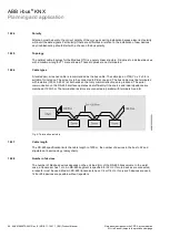
A twisted pair, screened cable is recommended as the bus cable. The cable type J-Y(St)Y n x 2 x 0.8 is
suitable, for instance. The screen is to be connected to PE at one end. The bus cable must be terminated
with resistors (120 Ω, 0.25 W) at both ends so that only minimal reflections are produced. The serial
communication on the RS-485 interface operates most efficiently if the source and load impedance are
matched at 120 Ohm. The termination resistors are connected in parallel with terminals A and B.
Fig. 9: Termination resistors
12.2.7
Cable length
The RS-485 specification limits the cable length to 1200 m, the number of devices in the bus to 32 and
stipulates a linear topology (daisy chain).
12.2.8
Number of devices
The number of Modbus devices depends on the unit load (UL) of the RS-485 transceivers. In the worst
case, a transceiver has 1 UL. An RS-485 segment is specified for 32 UL. If more devices are connected,
a repeater must be used. Modern RS-485 transceivers have 1/4 or 1/8 UL. If only such devices are used,
128 or 256 devices are possible without repeaters.
9A
K
K
10
846
4A
055
1


