


Turbocharger VTR..4
Seite / Page 5
Vorbemerkungen
Kap. / Chap. 0
Preliminary remarks
ABB Turbo Systems Ltd
10034
- H -
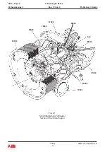
2 Funktionsbe schreibung
Der Turbolader besteht aus zwei Strömungsmaschi-
nen, einer Turbine und einem Verdichter, die auf einer
gemeinsamen Welle angebracht sind.
Die Abgase des Dieselmotores strömen durch das
Gaseintrittsgehäuse (51000) und den Düsenring
(56001).
Die Turbine (29000) nutzt die im Abgas enthaltene
Energie zum Antrieb des Verdichterrades (25000),
wobei durch den Verdichter Frischluft angesaugt und
vorverdichtete Luft in die Zylinder gedrückt wird.
Die Abgase gelangen durch das Gasaustrittsgehäuse
(61000) und durch die Abgasleitung ins Freie.
Die Luft, die für den Betrieb des Diesel motors benötigt
und im Turbolader verdichtet wird, gelangt durch den
Saugstutzen oder den Schall dämpfer (81000) in das
Verdichterrad (25000). Sie durchströmt den Diffu-
sor (79000) und verlässt den Turbolader durch den
Druck stutzen am Verdichtergehäuse (72000).
Die Zwischenwand (23000) trennt den Luft raum vom
Gasraum. Durch den Kanal (X) wird Sperrluft vom
Verdichter zur Laby rinthdichtung des Turbinenrotors
geleitet. Die Dichtung verhindert, dass Abgase in
den Ausgleichkanal (Z) und den Lager raum strömen
können.
Die Kanäle Y (Verdichterseite) und Z (Turbinenseite)
ermöglichen den Druckausgleich der Lagerräume und
verhindern Ölverluste.
Der Rotor läuft in elastisch abgestützten Wälzlagern,
die an beiden Enden leicht zugänglich sind. Jede
Lagerstelle hat eine eigene Schmiervorrichtung. Die
Lager raumdeckel haben je eine Öffnung zum Ölein-
füllen und Ölablassen. Ein Schauglas pro Lagerraum-
deckel gewährt Einblick in den Lagerraum.
2 Mode of operation
The turbocharger consists of two machines, a turbine
and a compressor which are mounted on a common
shaft.
The exhaust gases of the diesel engine flow through
the gas inlet casing (51000) and the nozzle ring
(56001).
The turbine uses the energy contained in the exhaust
gas to drive the compressor wheel (25000), whereby
the compressor draws in fresh air and precompressed
air is forced into the cylinders.
The exhaust gases are led into the open air through
the gas outlet casing (61000) and the exhaust pipes.
The air which is necessary for the operation of the
diesel engine and which is compressed in the tur-
bocharger passes through the suction branch or the
silencer (81000), into the compressor wheel (25000).
It then passes through the diffuser (79000) and leaves
the turbocharger through the volute of the air outlet
housing (72000).
The partition wall (23000) separates the air from the
gas. Sealing air from the compressor is led into the
labyrinth seal of the turbine rotor through the channel
(X). The seal prevents exhaust gases from flowing
into the compensation channel (Z) and the bearing
space.
The channels Y (compressor side) and Z (turbine
side) provide pressure compensation in the bearing
spaces and prevent oil loss.
The rotor runs in elastically mounted rolling contact
bearings which are easily accessible at either end.
Each bearing point has its own lubrication device.
The bearing space covers have openings for filling
and draining oil. One sightglass in each bearing space
cover allows inspection of the bearing space.
Summary of Contents for HT844662
Page 4: ......
Page 5: ...0 Preliminary remarks Vorbemerkungen ...
Page 6: ......
Page 18: ......
Page 19: ...1 Instructions on safety and hazards Sicherheits und Gefahrenhinweise ...
Page 20: ......
Page 34: ......
Page 35: ...2 Putting into operation Inbetriebnehmen ...
Page 36: ......
Page 53: ...3 Operation and maintenance Betrieb und Unterhalt ...
Page 54: ......
Page 99: ...Troubleshooting Beheben von Störungen 4 ...
Page 100: ......
Page 107: ...Disassembly and assembly Demontage und Montage 5 ...
Page 108: ......
Page 162: ......
Page 163: ...Taking out of operation Ausserbetriebnehmen 6 ...
Page 164: ......
Page 180: ......
Page 181: ...Appendix Anhang 7 ...
Page 182: ......
Page 184: ... 10036 ABB Turbo Systems Ltd E Seite Page 2 ABB Turbocharger VTR 4 Anhang Kap Chap 7 Appendix ...
Page 228: ...Approved lubricating oils Zugelassene Schmieröle 8 1 ...
Page 229: ......
Page 234: ...ABB Turbo Systems AG Bruggerstrasse 71a CH 5400 Baden Switzerland ABB ...


