


L2234
Emax
81/158
Model
Scale
Page No.
Doc. No.
Apparatus
1SDH000460R0002
L2778
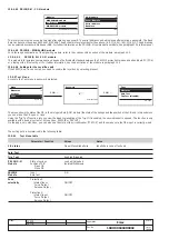
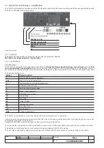
As a result, the currents in the circuit-breaker will be defined as "forward" or "backward" if their are in phase or out of phase with the previously-
defined power flow (for the default setting, see par. 14.4.4).
In short:
Example:
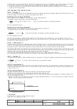
Once the power flow has been set as "Top
→
Bottom", the direction of the figure alongside is:
positive reactive power in
→
"forward" direction;
negative reactive power in
→
"backward" direction;
If the preset trip times were t
7FW
= 200ms and t
7BW
= 400ms, in this this case the
relay would have opened the circuit-breaker after t
7FW
= 200ms.
Note:
-
With the directional protection D activated, if the direction of the power cannot be determined the relay takes effect considering shorter of
the programmed times between t
7
fw and t
7
bw.
-
This protection works on the basis of the phase currents, not the neutral current.
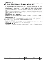
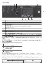
14.2.9.4.1 Start-up threshold “D”
The function can be enabled from the menu (see description of the protection menu 14.5.2)
The function behaves in exactly the same way as the protection "S" (see par. 14.2.9.2.2).
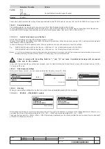
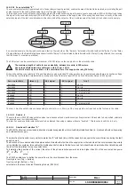
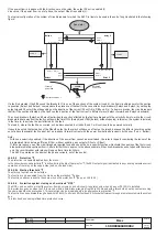
14.2.9.4.2 "D" (directional) zone selectivity
The Directional Zone Selectivity (SdZ D) function is particularly useful in ring and grid type systems where, in addition to the zone, it is essential
to define the direction of the power flow that powers the fault.
The SdZ D can be set as an alternative to Zone Selectivity S and G and requires an auxiliary power supply.
To define the zone and power flow, each relay has two inputs (DFin and DBin) and two outputs (Dfout and DBout), which must be suitably
connected to the other relays (see example below).
As in the SdZ S and G, the relays interact with each other, sending cutout signals via the outputs and reading them via the inputs.
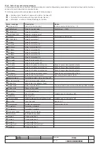
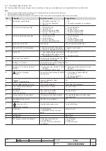
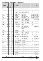
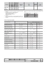
The general behavior is summarized in the table below.
(Example with power flow setting "Top
→
Bottom”).
Ifault (I
f
)
Power flow set
Power flow set
Top
→
Bottom
Bottom
→
Top
Value
Direction
Trip T
Trip T
I
f
< I
7
Either
No trip
No trip
I
f
> I
7
High
→
Low
t
7FW
t
7BW
I
f
> I
7
Low
→
High
t
7BW
t
7FW
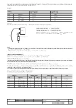
CB
Z
V
I
Inductive/resistive load
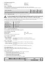
Ifault (I
f
)
Outputs status
Inputs status
T trip
Value
Direction
DFout
DBout
DFin
DBin
I
f
< I
7
either
0
0
either
either
No trip
I
f
> I
7
Top
→
Bottom
1
0
0
either
t
s
I
f
> I
7
Top
→
Bottom
1
0
1
either
t
7FW
I
f
> I
7
Bottom
→
Top
0
1
either
1
t
7BW
I
f
> I
7
Bottom
→
Top
0
1
either
0
t
s


