L2234
Emax
64/158
Model
Scale
Page No.
Doc. No.
Apparatus
1SDH000460R0002
L2778
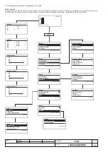
13.5 Operating instructions / Operation in service
13.5.1 Menu
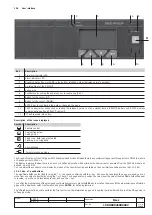
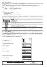
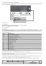
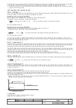
As seen previously, the PR122/P uses the display to show messages, diagrams and menus. These are organized in a logical and intuitive way.
The following is a general layout showing how to access the main menu pages in Maximum configuration (PR120/V installed).
10:22:53
---
Current
I1 :
- - -
I2 :
- - -
I3 :
- - -
Ne :
- - -
Ig :
- - -
Voltage
U1 :
- - -
U2 :
- - -
U3 :
- - -
U3 :
- - -
U12 :
- - -
U23 :
- - -
U31 :
- - -
Active Power
P1 :
- - -
P2 :
- - -
P3 :
- - -
P :
- - -
Reactive Power
Q1 :
- - -
Q2 :
- - -
Q3 :
- - -
Q :
- - -
Apparent Power
S1 :
- - -
S2 :
- - -
S3 :
- - -
S :
- - -
1/6
CB open
Auto Test
Trip Test (disabled)
CB status
Test
6/6
Device test
SIGNALLING module
COM module
Zone selectivity
Test
1/5
Protections settings
Measurements
Settings
Protections
Menu
Trip, measures, log
Power factor
Energy
Historicals
Measurements
1/7
2/5
Measures, graphics, harmonics
Measurements
Settings
Protections
Menu
Main Frequency
Contact W
ear
Peak factor
Measurements
6/7
0.0 %
3/5
General settings
Measurements
Settings
Protections
Menu
Main Frequency
Modules
Circuit Breaker
Settings
3/9
Optional modules
System
Display Contr
ast
Harmonic dist.
Settings
8/9
30%
4/5
Device test
Settings
Test
Measurements
Menu
5/5
Product information
Test
About
Settings
Menu
1/2
Protection Unit
About
Protection Unit
Circuit Breaker
U1 U2 U3 L1 L2 L3 LN

