


6
Electromagnetic Flowmeter COPA-XT
3.2.2 Installations in Larger Size Pipelines
The flowmeter can readily be installed in larger size pipe lines
through the use of flanged transition sections (e.g. Flanged
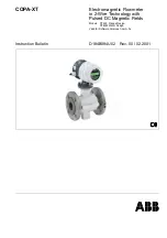
Reducers per DIN 28545). The pressure drop resulting from the
reduction can be determined from the Nomograph Fig. 10.
The pressure drop can be determined using the following
procedure:
1. Calculate the diameter ratio d/D.
2. Calculate the flow velocity as a function of the meter size
and the flow rate:
The flow velocity can also be determined from a Flow Rate
Nomograph, see Specification Sheet.
3. The pressure drop can be read on the -Y- axis at the
intersection of the “Flow Velocity” curve and the "Diameter
Ratio d/D" value on -X- axis in Fig. 10.
d
=
EMF inside diameter
D
=
Pipe inside diameter
v
=
Flow velocity in (m/s)
∆
p
=
Pressure drop in mbar
Flanged Reducer
Diameter Ratio d/D
Pres
su
re D
rop
∆
p [
m
ba
r]
Pressure Drop Diagram for EMF
Flanged reducer with
α
/2 = 8°
Fig. 10
Nomograph for Pressure Drop Determinations