


6
English
I
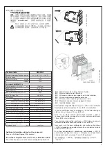
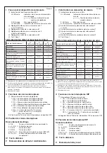
Front view with operating controls
햲
Indication of operational states with LEDs
U: green LED
- Status indication of control supply
voltage
V
Control supply voltage applied
F: red LED
- Fault message
R: yellow LED
- Status indication of the output relays
햳
Adjustment of the tens figure of the threshold value 1
(=warning)
햴
Adjustment of the units figure of the threshold value 1
햵
Adjustment of the tens figure of the threshold value 2
(= prewarning)
햶
Adjustment of the units figure of the threshold value 2
햷
Test / Reset
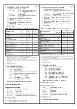
LEDs, status information and fault messages
Operational state
U:
green LED
F:
red LED
R:
yellow LED
Start-up
W
OFF
OFF
No fault
V
OFF
-- 1)
Prewarning
V
W
W
Insulation fault
(below threshold value)
V
V
-- 1)
w
/KE wire interruption
V
U
-- 1)
L+/L- wire interruption during
system start-up / test function
W
/
X
S
-- 1)
System leakage capacitance too
high / invalid measurement result
V
T
-- 1)
Internal system fault
-- 1)
X
-- 1)
Setting fault 2)
W
W
W
Test function
X
OFF
-- 1)
No fault after fault storage 3)
V
-- 4)
X
1) Depending on the configuration (see function diagrams)
2) Possible faulty setting: The threshold value for warning is set at a higher value
than the threshold value for prewarning.
3) The device has triggered after an insulation fault. The fault has been stored and
the insulation resistance has returned to a higher value than the threshold value
plus hysteresis.
4) Depending on the fault
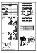
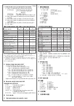
II DIP switch functions
햸
DIP switches for the adjustment of:
1 ON = Closed-circuit principle
OFF = Open-circuit principle
2 ON = Non-volatile fault storage ON
OFF = Non-volatile fault storage OFF
3 ON = Interrupted wire detection ON
OFF = Interrupted wire detection OFF
4 ON = 2 threshold values (2 x 1 c/o contact)
OFF = 1 threshold value (1 x 2 c/o contacts)
(R2.x disabled)
Default setting: All DIP switches in position OFF
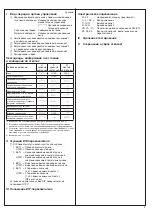
III DIP switch position
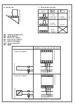
Electrical connection
A1-A2
Control supply voltage U
s
L+, L-, KE,
w
Measuring input
11-12/14
Output relay 1
21-22/24
Output relay 2
VS, V1+, V1-
Connection for coupling unit CM-IVN
S1, S2, S3
Control inputs, volt-free triggering
IV Remote
test
V
Fault storage and reset
Deutsch
I
Frontansicht mit Bedienelementen
햲
Betriebszustandsanzeige mit LEDs
U: LED grün
- Anzeige der Steuerspeisespannung
V
Steuerspeisespannung
liegt an
F: LED rot
- Fehlermeldung
R: LED gelb
- Anzeige der Schaltstellung der Aus-
gangsrelais
햳
Einstellung der 10er Stelle des Schwellwertes 1
(= Warnen)
햴
Einstellung der 1er Stelle des Schwellwertes 1
햵
Einstellung der 10er Stelle des Schwellwertes 2
(= Vorwarnen)
햶
Einstellung der 1er Stelle des Schwellwertes 2
햷
Test / Reset
LEDs, Statusinformationen und Fehlermeldungen
Betriebszustand
U:
LED grün
F:
LED rot
R:
LED gelb
Start-up
W
aus
aus
Kein Fehler
V
aus
-- 1)
Vorwarnen
V
W
W
Isolationsfehler
(Schwellwert unterschritten)
V
V
-- 1)
w
/KE-Leitungsbruch
V
U
-- 1)
L+/L- Leitungsbruch bei
Systemstart / Testfunktion
W
/
X
S
-- 1)
Netzableitkapazität zu hoch /
ungültiges Messergebnis
V
T
-- 1)
Interner Systemfehler
-- 1)
X
-- 1)
Einstellfehler 2)
W
W
W
Testfunktion
X
aus
-- 1)
Kein Fehler nach
Fehlerspeicherung 3)
V
-- 4)
X
1) Abhängig von der Konfiguration (siehe Funktionsdiagramme)
2) Mögliche Fehleinstellung: Der Schwellwert für Warnen ist auf einen größeren
Wert als der Schwellwert für Vorwarnen eingestellt.
3) Gerät hat nach einem Isolationsfehler ausgelöst. Der Fehler ist gespeichert
und der Isolationswiderstand ist wieder über den Schwellwert plus Hysterese
zurückgekehrt.
4) Abhängig vom Fehler
II DIP-Schalterstellungen
햸
DIP-Schalter zur Einstellung von:
1 ON = Ruhestromprinzip
OFF = Arbeitsstromprinzip
2 ON = Nullspannungssichere Fehlerspeicherung EIN
OFF = Nullspannungssichere Fehlerspeicherung AUS
3 ON = Leitungsbrucherkennung EIN
OFF = Leitungsbrucherkennung AUS
4 ON = 2 Schwellwerte (2 x 1 Wechsler)
OFF = 1 Schwellwert (1 x 2 Wechsler)
(R2.x ohne Funktion)
Auslieferzustand: Alle DIP-Schalter in Position OFF
III DIP-Schalterposition
Elektrischer Anschluss
A1-A2
Steuerspeisespannung U
s
L+, L-, KE,
w
Messeingang
11-12/14
Ausgangsrelais 1
21-22/24
Ausgangsrelais 2
VS, V1+, V1-
Anschluss für Vorschaltmodul CM-IVN
S1, S2, S3
Steuereingänge, potentialfreie Ansteuerung
IV Remote-Test
V
Fehlerspeicherung und Reset