


Pos: 2 /Module/Titelseiten/Betriebsanleitung/Analyse/OI/ACX Q4 [2017] @ 121\mod_1572258134702_3101.docx @ 1459345 @ @ 1
—
A B B M E A S U R E M E N T & A N A L Y T I C S | CO M M I S S I O NI N G I N S T R U CT I O N | C I /A CX - E N R E V . D
ACX
Advanced CGA Solutions
—
ABB Automation GmbH
Measurement & Analytics
Stierstädter Str. 5
60488 Frankfurt am Main
Germany
Tel: +49 69 7930-4666
Email: [email protected]
abb.com/analytical
Analyzer System for Emission
Monitoring, Cement Applications
and Process Measurement
Measurement made easy
CI
/A
CX
-EN
Re
v.
D
0
2.
20
20
—
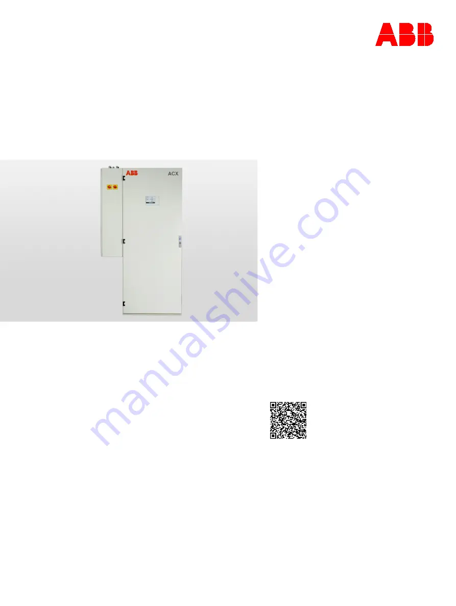
ACX
Introduction
ACX is a complete system solution for continuous
gas analysis.
The ACX system includes everything from probe,
heated lines, sample conditioning to reliable and
time-tested analyzers of the Advance Optima
series. It can be operated from the outside.
The system is available in various variants tailored
to your measuring tasks - emission monitoring,
cement applications and process gas
measurements.
It is especially designed for easy service and
maintenance.
Additional Information
Additional documentation on ACX is available for
download free of charge at www.abb.com/analytical.
Alternatively simply scan this code:
—
We reserve the right to make technical changes or modify the contents of this document
without prior notice. With regard to purchase orders, the agreed particulars shall prevail.
ABB does not accept any responsibility whatsoever for potential errors or possible lack of
information in this document.
We reserve all rights in this document and in the subject matter and illustrations contained
therein. Any reproduction, disclosure to third parties or utilization of its contents – in whole
or in parts – is forbidden without prior written consent of ABB.
© ABB 2020
3KXG141002R4401
=== Ende der Liste für Textmarke Cover ===


