


•
STO response times:
•
STO reaction time (shortest detectable break): 1 ms
•
STO response time:
-
Frames R1i…R7i: 2 ms (typical), 5 ms (maximum)
-
Frame R8i and multiples: 2 ms (typical), 25 ms (maximum)
•
Fault detection time: Channels in different states for longer than 200 ms
•
Fault reaction time: Fault detection time + 10 ms
•
Indication delays:
•
STO fault indication (parameter
31.22
) delay: < 500 ms
•
STO warning indication (parameter
31.22
) delay: < 1000 ms
■
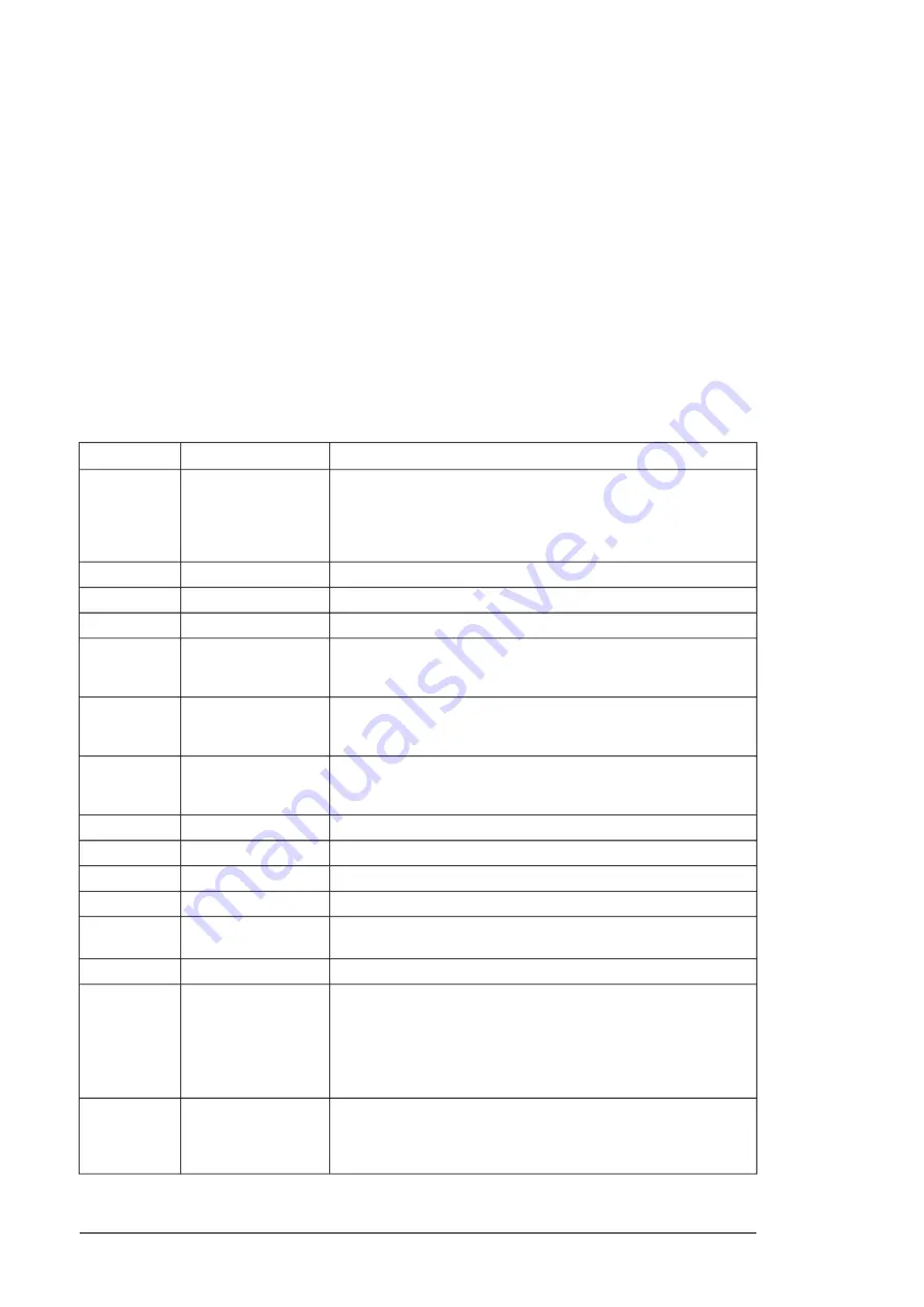
Abbreviations
Description
Reference
Abbr.
Classification of the safety-related parts of a control system in respect
of their resistance to faults and their subsequent behavior in the fault
condition, and which is achieved by the structural arrangement of the
parts, fault detection and/or by their reliability. The categories are: B,
1, 2, 3 and 4.
EN ISO 13849-1
Cat.
Common cause failure (%)
EN ISO 13849-1
CCF
Diagnostic coverage
EN ISO 13849-1
DC
Hardware fault tolerance
IEC 61508
HFT
Mean time to dangerous failure: (Total number of life units) / (Number
of dangerous, undetected failures) during a particular measurement
interval under stated conditions
EN ISO 13849-1
MTTF
D
Average probability of dangerous failure on demand, that is, mean
unavailability of a safety-related system to perform the specified safety
function when a demand occurs
IEC 61508
PFD
avg
Average frequency of dangerous failures per hour, that is, average
frequency of a dangerous failure of a safety related system to perform
the specified safety function over a given period of time
IEC 61508
PFH
Performance level. Levels a…e correspond to SIL
EN ISO 13849-1
PL
Systematic capability
IEC 61508
SC
Safe failure fraction (%)
IEC 61508
SFF
Safety integrity level (1…3)
IEC 61508
SIL
Maximum SIL (level 1…3) that can be claimed for a safety function
or subsystem
IEC/EN 62061
SILCL
Safe torque off
IEC/EN 61800-5-2
STO
Proof test interval. T
1
is a parameter used to define the probabilistic
failure rate (PFH or PFD) for the safety function or subsystem. Per-
forming a proof test at a maximum interval of T
1
is required to keep
the SIL capability valid. The same interval must be followed to keep
the PL capability (EN ISO 13849) valid.
IEC 61508-6
T
1
See also section Maintenance.
Mission time: the period of time covering the intended use of the safety
function/device. After the mission time elapses, the safety device must
be replaced. Note that any T
M
values given cannot be regarded as a
guarantee or warranty.
EN ISO 13849-1
T
M
198 The Safe torque off function
Summary of Contents for ACS880-107
Page 1: ... ABB INDUSTRIAL DRIVES ACS880 107 inverter units Hardware manual ...
Page 2: ......
Page 4: ......
Page 10: ...10 ...
Page 64: ...2 4 5 6 7 8 11 10 3 a b a b b 1 5 a 64 Electrical installation ...
Page 69: ...Electrical installation 109 5 6 4 3 Electrical installation 69 11 ...
Page 70: ...7 a b d c 110 Electrical installation 7 8 8 8 9 9 70 Electrical installation ...
Page 75: ...2 11 b PE 10 7 5 6 8 a 360 grounding detail Electrical installation 75 11 ...
Page 89: ...With FDPI 02 modules OPEN TERMIN ATED 1 1 2 2 OPEN TERMINATED 3 Electrical installation 89 11 ...
Page 90: ...90 ...
Page 96: ...96 ...
Page 110: ...4 5 6 7 8 6 10 10 110 Maintenance ...
Page 118: ...2 3 7 9 a a c c c 6 8 b b d d 11 e e 118 Maintenance ...
Page 121: ...7 a b d c 110 Electrical installation 7 8 8 8 9 9 Maintenance 121 ...
Page 130: ...130 ...
Page 154: ...154 ...
Page 155: ...Circuit diagrams Refer to the circuit diagrams delivered with the unit 9 Circuit diagrams 155 ...
Page 156: ...156 ...
Page 159: ... Dimension drawing 400 mm wide cubicle R1i R4i 400 mm R6i R7i Dimensions and weights 159 ...
Page 161: ... Dimension drawing R8i without C128 or H353 bottom cable exit Dimensions and weights 161 ...
Page 162: ... Dimension drawing R8i without C128 or H353 top cable exit 162 Dimensions and weights ...
Page 163: ... Dimension drawing 2 R8i without C128 or H353 bottom cable exit Dimensions and weights 163 ...
Page 164: ... Dimension drawing 2 R8i without C128 or H353 top cable exit 164 Dimensions and weights ...
Page 165: ... Dimension drawing 3 R8i without C128 or H353 bottom cable exit Dimensions and weights 165 ...
Page 166: ... Dimension drawing 3 R8i without C128 or H353 top cable exit 166 Dimensions and weights ...
Page 167: ... Dimension drawing drive control unit DCU 300 mm Dimensions and weights 167 ...
Page 169: ...Inverter module cubicle with one R8i module top cable exit Dimensions and weights 169 ...
Page 182: ...182 ...
Page 200: ...200 ...


