60
11.4.
Additional Information for UL Approved Installations
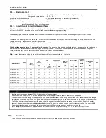
ACS255 is designed to meet the UL requirements. In order to ensure full compliance, the following must be fully observed.
Input Power Supply Requirements
Supply Voltage
500-600 Volts, + / - 10% variation allowed, Maximum 660 Volts RMS
Imbalance
Maximum 3% voltage variation between phase – phase voltages allowed
All ACS255 units have phase imbalance monitoring. A phase imbalance of > 3% will result in the drive tripping. For
input supplies which have supply imbalance greater than 3% (typically the Indian sub- continent & parts of Asia Pacific
including China) ABB Drives recommends the installation of input line reactors. Alternatively.
Frequency
50 – 60Hz + / - 5% Variation
Short Circuit Capacity
Voltage Rating
Min HP
Max HP
Maximum supply short-circuit current
600
1
20
100kA rms (AC)
All the drives in the above table are suitable for use on a circuit capable of delivering not more than the above
specified maximum short-circuit Amperes symmetrical with the specified maximum supply voltage.
Incoming power supply connection must be according to section 5.9
All ACS255 units are intended for indoor installation within controlled environments which meet the condition limits shown in section 11.1 on
page 59.
Branch circuit protection must be installed according to the relevant national codes. Fuse ratings and types are shown in section 11.2 on page
59.
Suitable Power and motor cables should be selected according to the data shown in section 11.2 on page 59.
Power cable connections and tightening torques are shown in section 4.4 on page 15.
ACS255 provides motor overload protection in accordance with the National Electrical Code (US).
Where a motor thermistor is not fitted, or not utilised, Thermal Overload Memory Retention must be enabled by setting 3005
THERMAL OVERLOAD VALUE RETENTION = 1
Where a motor thermistor is fitted and connected to the drive, connection must be carried out according to the information shown in
section 5.7.2
11.5.
Derating Information
Derating of the drive maximum continuous output current capacity is required when
Operating at ambient temperature in excess of 40°C / 104°F
Operating at Altitude in excess of 1000m/ 3281 ft
Operation with Effective Switching Frequency higher than the minimum setting
The following derating factors should be applied when operating drives outside of these conditions
11.5.1.
Derating for Ambient Temperature
Enclosure Type
Maximum Temperature
Without Derating.
(UL Approved)
Derate by
Maximum Permissible Operating
Ambient Temperature with
Derating (Non UL Approved)
IP20
50°C / 122°F
N/A
50°C
IP66
40°C / 104°F
2.5% per °C (1.8°F)
50°C
11.5.2.
Derating for Altitude
Enclosure Type
Maximum Altitude
Without Derating
Derate by
Maximum Permissible
(UL Approved)
Maximum Permissible
(Non-UL Approved)
IP20
1000m / 3281ft
1% per 100m / 328 ft
2000m / 6562 ft
4000m / 13123 ft
IP66
1000m / 3281ft
1% per 100m / 328 ft
2000m / 6562 ft
4000m / 13123 ft
11.5.3.
Derating for Switching Frequency
Switching Frequency (Where available)
Enclosure Type
4kHz
8kHz
12kHz
16kHz
24kHz
32kHz
IP20
N/A
N/A
20%
30%
40%
50%
IP66
N/A
10%
25%
35%
50%
50%
11.5.4.
Example of applying Derating Factors
If a 5 HP IP66 drive is to be used at an altitude of 2000 metres above sea level, with 12kHz switching frequency and 45°C ambient temperature.
From the table above, we can see that the rated current of the drive is 9.5 Amps at 40°C,
Firstly, apply the switching frequency derating, 12kHz, 25% derating
9.5 Amps x 75% = 7.1 Amps
Now, apply the derating for higher ambient temperature, 2.5% per °C above 40°C = 5 x 2.5% = 12.5%
7.1 Amps x 87.5% = 6.2 Amps
Now apply the derating for altitude above 1000 metres, 1% per 100m above 1000m = 10 x 1% = 10%
7.9 Amps x 90% = 5.5 Amps continuous current available.
If the required motor current exceeds this level, it will be necessary to either:
-
Reduce the switching frequency selected
-
Use a higher power rated drive and repeat the calculation to ensure sufficient output current is available.


