


63
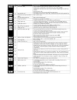
Fault Code
No.
Description
Corrective Action
13
Excessive DC Ripple
The DC Bus Ripple Voltage level can be displayed in parameter 0187
A historical log is stored at 20ms intervals prior to a trip in parameter 0194
Check all three supply phases are present and within the 3% supply voltage level imbalance
tolerance.
Reduce the motor load
If the fault persists, contact your local ABB Drives Sales Partner
14
Input phase loss trip
Drive intended for use with a 3 phase supply, one input phase has been disconnected or lost.
15
Instantaneous over current on drive
output.
Refer to fault 3 above
16
Faulty thermistor on heatsink.
Refer to your ABB Sales Partner.
17
Internal memory fault.
Parameters not saved, defaults reloaded.
Try again. If problem recurs, refer to your ABB Authorised Distributor.
18
4-20mA Signal Lost
The reference signal on Analog Input 1 or 2 (Terminals 6 or 10) has dropped below the
minimum threshold of 3mA. Check the signal source and wiring to the ACS255 terminals.
19
Internal memory fault.
Parameters not saved, defaults reloaded.
Try again. If problem recurs, refer to your ABB Authorised Distributor.
21
Motor PTC Over Temperature
The connected motor PTC device has caused the drive to trip
22
Cooling Fan Fault
Check and if necessary, replace the drive internal cooling fan
23
Ambient Temperature too High
The measured temperature around the drive is above the operating limit of the drive.
Ensure the drive internal cooling fan is operating
Ensure that the required space around the drive as shown in section 4.5 and 4.7 has been
observed, and that the cooling airflow path to and from the drive is not restricted
Increase the cooling airflow to the drive
Reduce the effective switching frequency setting in parameter 2606.
Reduce the load on the motor / drive
24
Maximum Torque Limit Exceeded
The output torque limit has exceeded the drive capacity or trip threshold
Reduce the motor load, or increase the acceleration time
26
Drive output fault
Drive output fault
29
Internal STO circuit Error
Refer to your ABB Sales Partner
40
Autotune Failed
Measured motor stator resistance varies between phases. Ensure the motor is correctly
connected and free from faults. Check the windings for correct resistance and balance.
41
Measured motor stator resistance is too large. Ensure the motor is correctly connected and
free from faults. Check that the power rating corresponds to the power rating of the
connected drive.
42
Measured motor inductance is too low. Ensure the motor is correctly connected and free
from faults.
43
Measured motor inductance is too large. Ensure the motor is correctly connected and free
from faults. Check that the power rating corresponds to the power rating of the connected
drive.
44
Measured motor parameters are not convergent. Ensure the motor is correctly connected
and free from faults. Check that the power rating corresponds to the power rating of the
connected drive.
49
Output (Motor) Phase Loss
One of the motor output phases is not connected to the drive.
50
Modbus comms fault
A valid Modbus telegram has not been received within the watchdog time limit set in
parameter 3018.
Check the network master / PLC is still operating
Check the connection cables
Increase the value of parameter 3019 to a suitable level
51
CAN Open comms trip
A valid CAN open telegram has not been received within the watchdog time limit set in
parameter 3018
Check the network master / PLC is still operating
Check the connection cables
Increase the value of parameter 3018 to a suitable level
53
IO card comms trip
Internal communication to the inserted Option Module has been lost.
Check the module is correctly inserted


