


26
5.10.7.
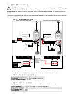
“STO” Electrical Installation
The “STO” wiring shall be protected from inadvertent short circuits or tampering which could lead to failure of the “STO” input signal,
further guidance is given in the diagrams below.
In addition to the wiring guidelines for the “STO” circuit below, section 5.1.1 “Recommended installation for EMC compliance should also be
followed.
The drive should be wired as illustrated below; the 24Vdc signal source applied to the “STO” input can be either from the 24Vdc on the drive or
from an External 24Vdc power supply.
5.10.7.1.
Recommended “STO” wiring
Using an External 24Vdc Power Supply.
Using the drives on-board 24Vdc supply
- Twisted-Pair
- Shielded cables
1213
0V
+24Vdc
Safety relay
Protective Capped Trunking
or equivalent to prevent
STO Cable short circuit to an
external Voltage source.
External
Power
Supply
Protected
shielded cables
1213
Protective Capped Trunking
or equivalent to prevent
STO Cable short circuit to an
external Voltage source.
1
7
Safety
relay
Note : The Maximum cable length from Voltage source to the drive terminals should not exceed 25 metres.
5.10.7.2.
External Power supply Specification.
Voltage Rating (Nominal)
24Vdc
STO Logic High
18-30Vdc (Safe torque off in standby)
Current Consumption (Maximum)
100mA
5.10.7.3.
Safety Relay Specification.
The safety relay should be chosen so that at minimum it meets the safety standards in which the drive meets.
Standard Requirements
SIL2 or PLd SC3 or better (With Forcibly guided Contacts)
Number of Output Contacts
2 independent
Switching Voltage Rating
30Vdc
Switching Current
100mA
Wires should be
protected
against short
circuits as
shown above
1 2 3 4 5 6 7 8 9 10 11 12 13
0V
+24Vdc
External
Power
Supply
Safety relay
1 2 3 4 5 6 7 8 9 10 11 12 13
Safety relay


